


TMP92CZ26A
92CZ26A-185
3.8.3 Basic functions and register setting
In this section, setting of the block address area, the connecting memory and the number
of waits out of the memory controller’s functions are described.
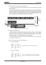
(1) Block address area specification
The block address areas of CS0 to CS3 are specified by MSAR0 to MSAR3 and MAMR0 to
MAMR3.
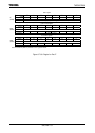
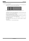
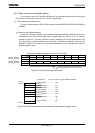
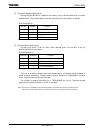
(a) Memory start address register
Figure 3.8.1 shows the memory start address registers. MSAR0 to MSAR3 set the start
addresses for the CS0 to CS3 areas. Set the upper eight bits (A23 to A16) of the start
address in <S23:16>. The lower 16 bits of the start address (A15 to A0) are permanently set
to 0. Accordingly, the start address can only be set in 64-Kbyte increments, starting from
000000H.
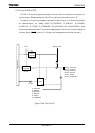
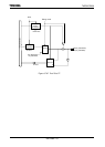
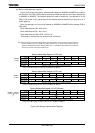
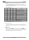
Figure 3.8.2 shows the relationship between the start address and the start
address register value.
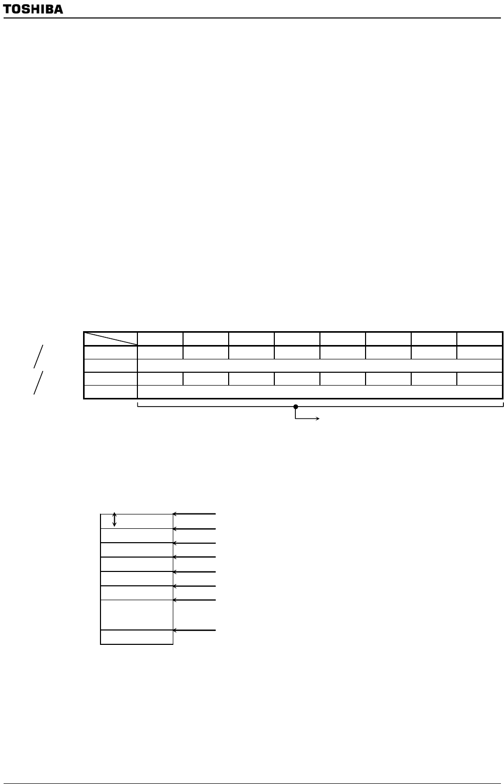
Memory Start Address Registers (for areas CS0 to CS3)
7 6 5 4 3 2 1 0
Bit symbol S23 S22 S21 S20 S19 S18 S17 S16
Read/Write R/W
After reset 1 1 1 1 1 1 1 1
Function Determines A23 to A16 of start address
Figure 3.8.1 Memory Start Address Register
64KByte
Address
000000H
FFFFFFH
000000H .................... 00H
010000H .................... 01H
020000H .................... 02H
030000H .................... 03H
040000H .................... 04H
050000H .................... 05H
060000H .................... 06H
FF0000H ................... FFH
Start Address Value in start address register (MSAR0 to MSAR3)
to to
Figure 3.8.2 Relationship between Start Address and Start Address Register Value
MSAR0
(0143H)
MSAR1
(0147H)
MSAR2
(014BH)
MSAR3
(014FH)
Sets start addresses for areas CS0 to CS3