


TMP92CZ26A
92CZ26A-626
3.25.4 Notes of Power sequence
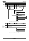
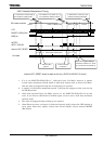
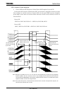
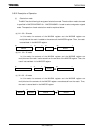
• Power ON/Power OFF Sequence (Initial Power ON/Complete Power OFF)
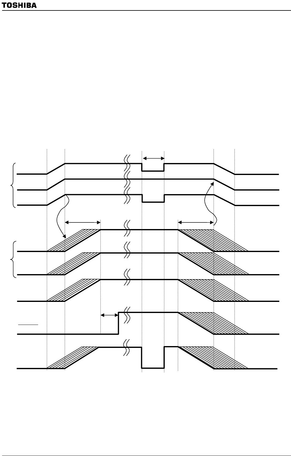
In the power ON sequence (initial power ON), power must be supplied to internal circuits
first and then to external circuits, as shown below. In the power OFF sequence (complete
power OFF), power must be turned off from external circuits so that internal circuits are
turned off last.
Power ON
(DVCC1A, DVCC1B, DVCC1C) → (DVCC3A, DVCC3B, AVCC)
Power OFF
(AVCC, DVCC3A, DVCC3B) → (DVCC1C, DVCC1B, DVCC1A)
Note1: Although it is possible to turn on or off 1.5V and 3.0V rails simultaneously, external pins may temporarily
become unstable in this case. Therefore, if there is any possibility that this would affect external devices
connected with the TMP92CZ26A, external power supplies should be turned on or off while internal power
supplies are stable, as shown in the diagram above.
Note2: In the power ON sequence, 3V rails must not be turned on before 1.5V rails. In the power OFF sequence, 3V
rails must not be turned off after 1.5V rails.
Power increases and
stabilizes within 100 ms.
3.0V rails should be
turned off first, followed by
1.5V rails.
1.5V rails should be
turned on first, followed
b
y
3.0V rails.
Power decreases and
stabilizes within 100 ms.
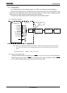
DVCC1A
DVCC1B
DVCC1C
RESET
AVCC
DVCC3B
DVCC3A
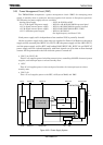
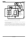
Oscillator Wake-up time to be stable
20 system clock
PWE terminal
Power Cut Mode
(
PMC
)
Power on
Power off