


TMP92CZ26A
92CZ26A-27
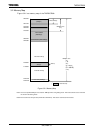
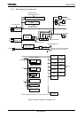
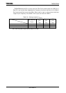
3.3.3 System clock controller
The system clock controller generates the system clock signal (f
SYS
) for the CPU core and
internal I/O.
SYSCR0<XEN> and SYSCR0<XTEN> control enabling and disabling of each oscillator.
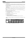
SYSCR1<GEAR2:0> sets the high frequency clock gear to either 1, 2, 4, 8 or 16 (fc, fc/2, fc/4,
fc/8, fc/16). These functions can reduce the power consumption of the equipment in which
the device is installed.
The combination of settings <XEN> = “1”, <SYSCK> = “0” and <GEAR2 to 0> = “100” will
be PLL-OFF mode and cause the system clock (f
SYS
) to be set to fc/16 after reset.
For example, f
SYS
is set to 625 kHz when the 10MHz oscillator is connected to the X1 and
X2 pins.
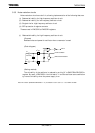
(1) Clock gear controller
f
SYS
is set according to the contents of the Clock Gear Select Register SYSCR1<GEAR2:
0> to either fc, fc/2, fc/4, fc/8 or fc/16. Using the clock gear to select a lower value of f
SYS
reduces power consumption.
(Example)
Changing clock gear
SYSCR1 EQU 10E1H
LD (SYSCR1),XXXXX001B ; Changes system clock f
SYS to
fc/2
LD (DUMMY),00H Dummy instruction
X: don't care
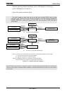
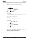
(High-speed clock gear changing)
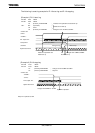
To change the clock gear, write the register value to the SYSCR1<GEAR2 to 0> register.
It is necessary the warming up time until changing after writing the register value.
There is the possibility that the instruction next to the clock gear changing instruction is
executed by the clock gear before changing. To execute the instruction next to the clock gear
switching instruction by the clock gear after changing, input the dummy instruction as
follows (instruction to execute the write cycle).
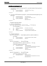
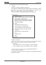
(Example)
SYSCR1 EQU 10E1H
LD (SYSCR1),XXXXX010B ; Changes f
SYS
to fc/4
LD (DUMMY),00H ; Dummy instruction
Instruction to be executed after clock gear changed