


TMP92CZ26A
92CZ26A-502
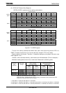
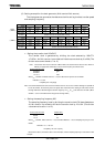
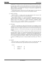
(2) Setting example for the clock generator (8-bit counter/6-bit counter)
The clock generator generates the reference clock for setting the data transfer speed
and sampling frequency.
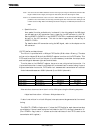
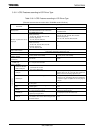
7 6 5 4 3 2 1 0
bit Symbol CK07 CK06 CK05 CK04 CK03 CK02 CK01 CK00
Read/Write R/W R/W R/W R/W R/W R/W R/W R/W
After reset 0 0 0 0 0 0 0 0
Function Divider value for CK signal (8-bit counter)
15 14 13 12 11 10 9 8
Bit symbol WS05 WS04 WS03 WS02 WS01 WS00
Read/Write R/W R/W R/W R/W R/W R/W
After reset 0 0 0 0 0 0
Function
Divider value for WS signal (6-bit counter)
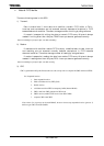
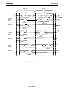
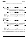
• Setting the transfer clock I2SnCKO
The transfer clock is generated by dividing the clock selected by I2SnCTL
<CLKSn>. An 8-bit counter is provided to divide the source clock by 3 to 256. (The
divider value cannot be set to 1 or 2.)
Note: The transfer clock must not exceed 10 MHz. Make sure that the transfer clock is set to within 10
MHz by an appropriate combination of source clock frequency and divider value.
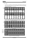
8-bit counter set value Divider value
00000000 256
00000001 1
11111111 255
When f
SYS
= 60 MHz and I2SnC<CKn7:0> = 150, the data transfer speed is set as follows:
I2SnCKO = f
SYS
/150
= 60 [MHz]/150 = 400 [kbps]
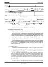
Note: It is recommended that the value to be set in I2SnC<CKn7:0> be an even number. Although it is possible to
set an odd number, the clock duty of the CK signal does not become 50%. Setting an odd number causes
the High width of the I2SnCK0 signal to become longer by one f
sys
or f
PLL
pulse than the Low width. (When
<EDGE> = 0, the Low width becomes longer than the High width.)
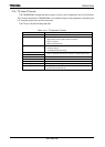
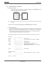
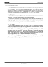
• Setting the sampling frequency WS
The sampling frequency is set by dividing the transfer clock (CK) described above.
A 6-bit counter is provided to divide the transfer clock by 16 to 64. (The divider
value cannot be set to 1 to 15.)
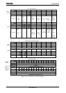
6-bit counter set value Divider value
000000 64
000001 1
111111 63
When f
SYS
= 60 MHz, I2SnC<CKn7:0> = 150, and I2SnC<WSn5:0> = 50, the sampling frequency is set as
follows:
I2SnCKO = f
SYS
/ 150 / 50
= 60 [MHz] / 150 / 50 = 8 [kHz]
Based on the above, the transfer clock is set to 400 kbps, and the sampling frequency is set to 8 kHz in this
example.
I2S0C
(180AH)
(180BH)