


TMP92CZ26A
92CZ26A-186
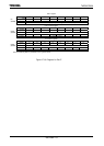
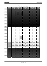
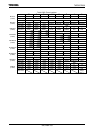
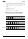
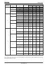
(b) Memory address mask registers
Figure 3.8.3 shows the memory address mask registers. MAMR0 to MAMR3 are used to
set the size of the CS0 to CS3 areas by specifying a mask for each bit of the start address set
in MAMR0 to MAMR3. The compare operation used to determine if an address is in the
CS0 to CS3 areas is only performed for bus address bits corresponding to bits set to 0 in
these registers.
Also, the address bits that can be masked by MAMR0 to MAMR3 differ between CS0 to
CS3 areas.
Block address area CS0 : A20 to A8
Block address area CS1 : A21 to A8
Block address area CS2 to CS3 : A22 to A15
Accordingly, the size that can be each area is different.
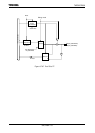
Note: After releasing reset, only the control register of the block address area 2 is valid. The control register of
the block address area 2 has <B2M> bit. Setting <B2M> bit to “0” sets the block address area 2 to
addresses 000000H to FFFFFFH. Setting <B2M> bit to “1” specifies the start address and the address
area size as it is in the other block address area.
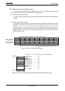
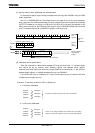
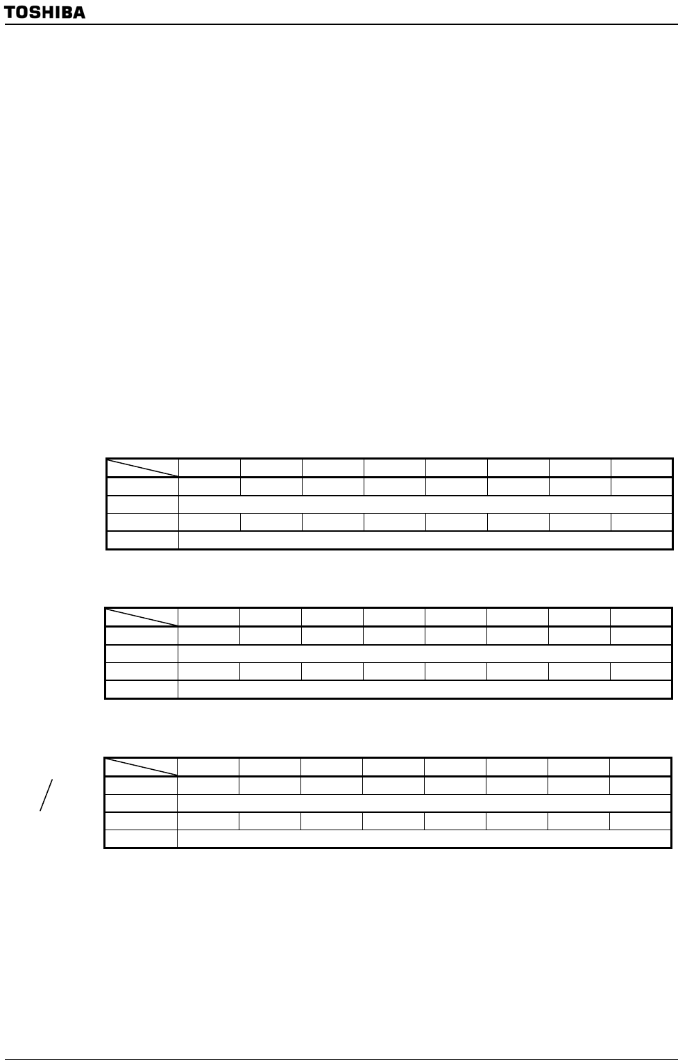
Memory Address Mask Register ( for CS0 area)
7 6 5 4 3 2 1 0
Bit symbol V20 V19 V18 V17 V16 V15 V14∼9 V8
Read/Write R/W
After reset 1 1 1 1 1 1 1 1
Function Sets size of CS0 area 0: Used for address compare
Range of possible settings for CS0 area size: 256Bytes to 2MBytes
Memory Address Mask Register ( for CS1 area)
7 6 5 4 3 2 1 0
Bit symbol V21 V20 V19 V18 V17 V16 V15∼9 V8
Read/Write R/W
After reset 1 1 1 1 1 1 1 1
Function Sets size of CS1 area 0: Used for address compare
Range of possible settings for CS1 area size: 256Bytes to 4MBytes
Memory Address Mask Register ( for CS2,CS3 area)
7 6 5 4 3 2 1 0
Bit symbol V22 V21 V20 V19 V18 V17 V16 V15
Read/Write R/W
After reset 1 1 1 1 1 1 1 1
Function Sets size of CS2 or CS3 area 0: Used for address compare
Range of possible settings for CS2 or CS3 area size: 32KBytes to 8MBytes
Figure 3.8.3 Memory Address Mask Registers
MAMR0
(0142H)
MAMR1
(0146H)
MAMR2
(014AH)
MSAR3
(014FH)