


TMP92CZ26A
92CZ26A-313
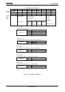
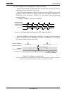
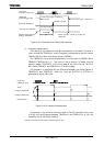
Figure 3.13.13 One-shot Pulse Output (without delay)
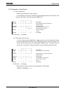
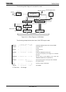
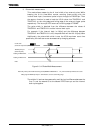
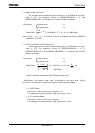
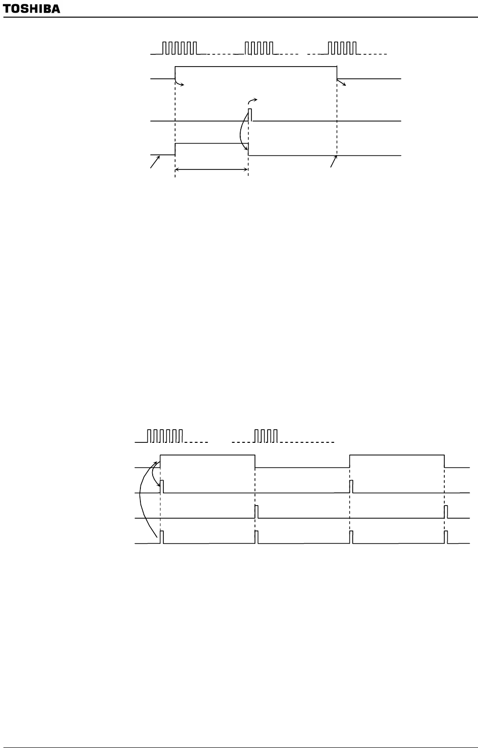
2. Frequency measurement
The frequency of the external clock can be measured in this mode. The clock is
input through the TB0IN0 pin, and its frequency is measured by the 8 bit timers
TMRA01 and the 16 bit timer/event counter (TMRB0).
The TB0IN0 pin input should be selected for the input clock of TMRB0. Set to
TB0MOD<TB0CPM1:0>=”11”. The value of the up counter is loaded into the
capture register TB0CP0H/L at the rising edge of the timer flip-flop TA1FF of
8bit timers (TMRA01), and TB0CP1H/L at its falling edge.
The frequency is calculated by the difference between the loaded values in
TB0CP0H/L and TB0CP1H/L when the interrupt (INTTA0 or INTTA1) is
generated by either 8 bit timer.
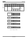
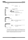
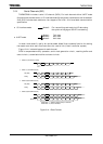
Figure 3.13.14 Frequency Measurement
For example, if the value for the level 1 width of TA1FF of the 8 bit timer is set
to 0.5[s] and the difference between TB0CP0H/L and TB0CP1H/L is 100, the
frequency will be 100/0.5[s] =200[Hz].
Note: The frequency in this examole is calculated with 50% duty.
c + p
c
Inversion enable
(p)
Pulse width
Load into capture register 0 (TB0CP0H/L)
INT6 occured
Count clock
(Prescaler output clock )
TB0IN0 iput
(External trigger pulse)
Match with TB0RG1H/L
Timer output pin TB0OUT0
Load into capture register 1 (TB0CP1H/L)
INTTB01 occured
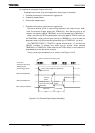
Enable inversioncaused by
loading to TB0CP0H/L
Disable inversion caused by loading into
TB0CP1H/L
C2
C1
C2
C1
C2
C1
Count clock
(TB0IN0 pin input)
TA1FF
Loading to TB0CP0H/L
Loading to TB0CP1H/L
INTTA0/INTTA1