


TMP92CZ26A
92CZ26A-556
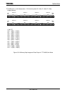
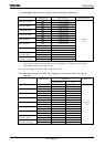
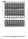
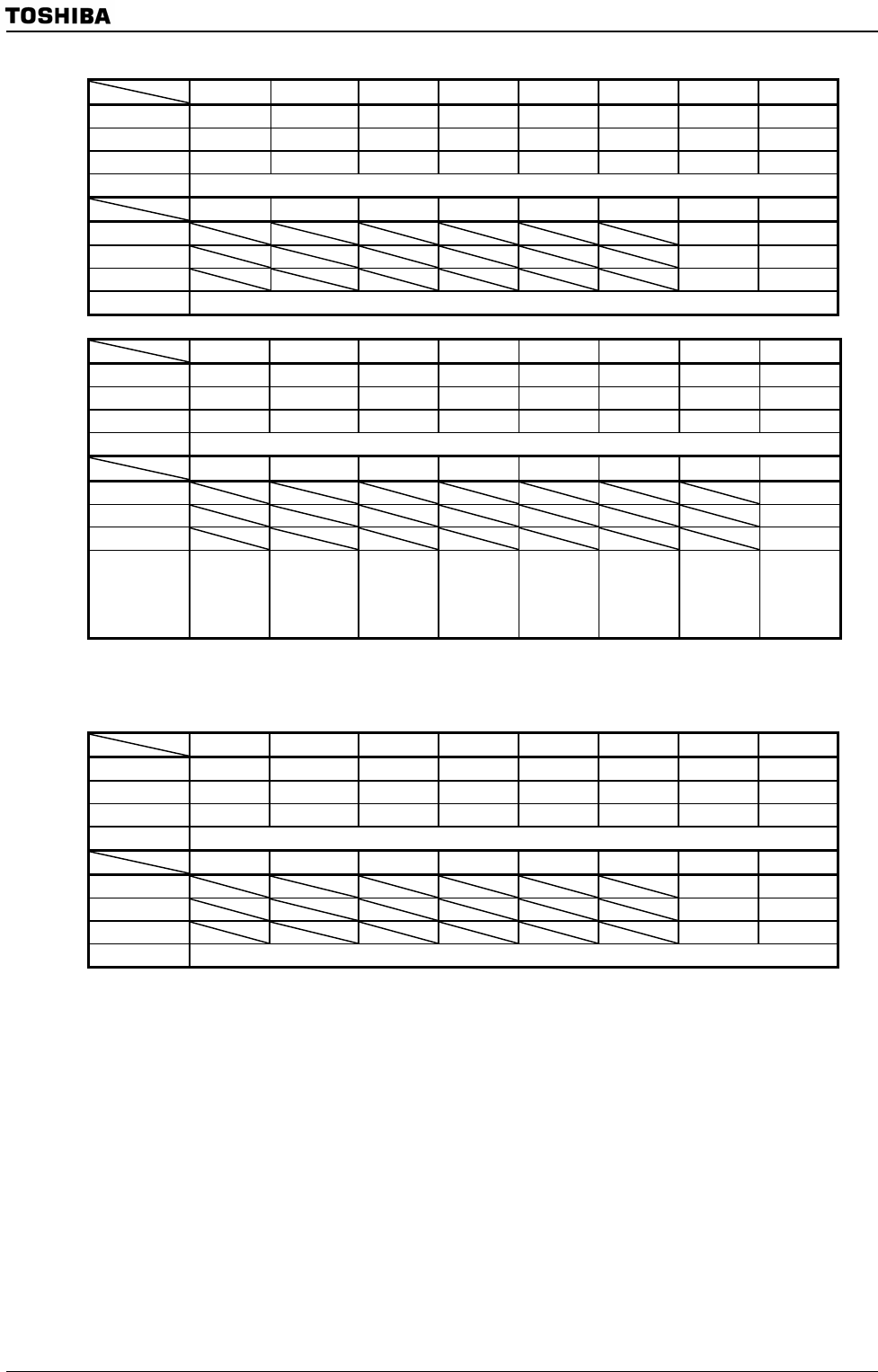
LCD Sub Area HOT Point Register (X-dir)
7 6 5 4 3 2 1 0
bit Symbol SAH7 SAH6 SAH5 SAH4 SAH3 SAH2 SAH1 SAH0
Read/Write R/W R/W R/W R/W R/W R/W R/W R/W
After reset 0 0 0 0 0 0 0 0
Function LCD sub area HOT point (7-0)
7 6 5 4 3 2 1 0
bit Symbol SAH9 SAH8
Read/Write R/W R/W
After reset 0 0
Function LCD sub area HOT point (9-8)
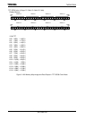
LCD Sub Area HOT Point Register (Y-dir)
7 6 5 4 3 2 1 0
bit Symbol SAHY7 SAHY6 SAHY5 SAHY4 SAHY3 SAHY2 SAHY1 SAHY0
Read/Write R/W R/W R/W R/W R/W R/W R/W R/W
After reset 0 0 0 0 0 0 0 0
Function LCD sub area HOT point (7-0)
7 6 5 4 3 2 1 0
bit Symbol SAHY8
Read/Write R/W
After reset 0
Function
LCD sub
area HOT
point
(9-8)
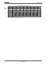
Note: The HOT point should be set in units of the specified number of dots, which is determined by the display
color mode and display RAM access data bus width.
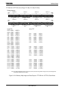
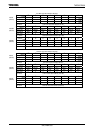
LCD Sub Area Display Segment Size Register
7 6 5 4 3 2 1 0
bit Symbol SAS7 SAS6 SAS5 SAS4 SAS3 SAS2 SAS1 SAS0
Read/Write R/W R/W R/W R/W R/W R/W R/W R/W
After reset 0 0 0 0 0 0 0 0
Function LCD sub area segment size (7-0)
7 6 5 4 3 2 1 0
bit Symbol SAS9 SAS8
Read/Write R/W R/W
After reset 0 0
Function LCD sub area segment size (9-8)
Note: The segment size should be set in units of the specified number of dots, which is determined by the display
color mode and display RAM access data bus width.
LSAHX
(02A8H)
(02A9H)
LSASS
(02ACH)
(02ADH)
LSAHY
(02AAH)
(02ABH)