


TMP92CZ26A
92CZ26A-621
3.25.2 Detailed Description of Operation
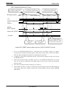
This section explains the procedures for entering and exiting the Power Cut Mode.
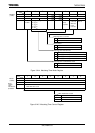
• Entering the Power Cut Mode
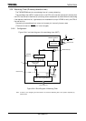
When to enter the Power Cut Mode, the CPU needs to be operating in the internal RAM.
Low frequency clock (XT) must be enable condition.
It is also necessary to disable interrupt requests, stop DMA operations, WDT and AD
converter. Next, set the output pins to function as ports through the Pn, PnCR and PnDR
registers. At this time, PM7 should be set as PWE. Of the external interrupt pins, those to be
used for waking up from the Power Cut Mode should be set as input pins with interrupt
enabled.
About trigger of interruption, only rising edges are effective among selectable interruption
pins. When INT4 is used as TSI, the de-bounce circuit should be disabled.
Then, set the warm-up time for waking up from Power Cut Mode in PMCCTL<WUTM1:0>.
Write the wake-up program at addresses from 46000H to 49FFFH in the internal RAM.
Should be written all initialize sequence including WDT in this program.
Finally, stop the PLL and set PMCCTL<PCM_ON> to “1” to enter the Power Cut Mode.
At this time, the RESET (HOT_RESET) signal is asserted for all the circuits excluding
external I/O and PMC.
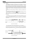
Note: As soon as PMCCTL<PCM_ON> is set to “1”, the power management signal (PWE) changes from “1” to “0”
and external power supplies are turned off.