


TMP92CZ26A
92CZ26A-266
3.12 8 Bit Timer (TMRA)
The TMP92CZ26A features 8 channel (TMRA0 to TMRA7) built-in 8-bit timers.
These timers are paired into 4 modules: TMRA01, TMRA23, TMRA45 and TMRA67. Each
module consists of 2 channels and can operate in any of the following 4 operating modes.
• 8-bit interval timer mode
• 16-bit interval timer mode
• 8-bit programmable square wave pulse generation output mode (PPG: Variable duty cycle
with variable period)
• 8-bit pulse width modulation output mode (PWM – Variable duty cycle with constant
period)
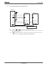
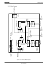
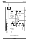
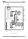
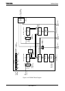
Figure 3.12.1 to Figure 3.12.4 show block diagrams for TMRA01 to TMRA67.
Each channel consists of an 8-bit up counter, an 8-bit comparator and an 8-bit timer register.
In addition, a timer flip-flop and a prescaler are provided for each pair of channels.
The operation mode and timer flip-flops are controlled by 5bytes registers SFRs
(Special-function registers).
Each of the 4 modules (TMRA01 to TMRA67) can be operated independently. All modules
operate in the same manner; hence only the operation of TMRA01 is explained here.
The contents of this chapter are as follows.
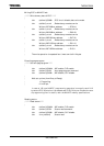
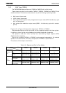
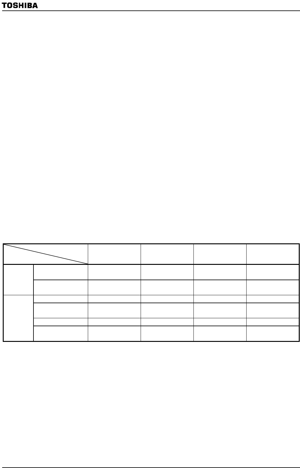
Table 3.12.1 Registers and Pins for Each Module
Module
Specification
TMRA01 TMRA23 TMRA45 TMRA67
Input pin for external
clock
TA0IN
(Shared with PC1)
TA2IN
(Shared with PC3)
Low-frequency clock
fs
Low-frequency clock
fs
External
pin
Output pin for timer
flip-flop
TA1OUT
(Shared with PM1)
TA3OUT
(Shared with PP1)
TA5OUT
(Shared with PP2)
TA7OUT
(Shared with PP3)
Timer run register TA01RUN (1100H) TA23RUN (1108H) TA45RUN (1110H) TA67RUN (1118H)
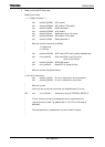
Timer register
TA0REG (1102H)
TA1REG (1103H)
TA2REG (110AH)
TA3REG (110BH)
TA4REG (1112H)
TA5REG (1113H)
TA6REG (111AH)
TA7REG (111BH)
Timer mode register TA01MOD (1104H) TA23MOD (110CH) TA45MOD (1114H) TA67MOD (111CH)
SFR
(Address)
Timer flip-flop
control register
TA1FFCR (1105H) TA3FFCR (110DH) TA5FFCR (1115H) TA7FFCR (111DH)