


TMP92CZ26A
92CZ26A-587
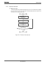
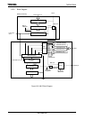
3.21.6 Explanation of the interrupt signal and alarm signal
Can use alarm function by setting of register of PAGE1 and output either of three signals
from
ALARM
pin as follows by write “1” to PAGER<PAGE>. INTRTC outputs 1shot pulse
when the falling edge is detected. RTC is not initializes by RESET. Therefore, when clock or
alarm function is used, clear interrupt request flag in INTC (interrupt controller).
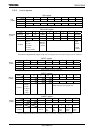
(1) In accordance of alarm register and the timer, output “0”.
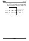
(2) Output clock of 1Hz.
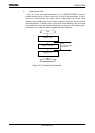
(3) Output clock of 16Hz.
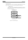
(1) In accordance with alarm register and a clock, output “0”
When value of a clock of PAGE0 accorded with alarm register of PAGE1 with a state
of PAGER<ENAALM>= “1”, output “0” to
ALARM pin and occur INTRTC.
Follows are ways using alarm.
Initialization of alarm is done by writing in “1” at RESTR<RSTALM>, setting value
of all alarm becomes don’t care. In this case, always accorded with value of a clock and
request INTRTC interrupt if PAGER<ENAALM> is “1”.
Setting alarm min., alarm hour, alarm day and alarm the day week are done by
writing in data at each register of PAGE1.
When all setting contents accorded, RTC generates INTRTC interrupt, if
PAGER<INTENA><ENAALM> is “1”. However, contents (don't care state) which does
not set it up is considered to always accord.
The contents, which set it up once, cannot be returned to don't care state in
independence. Initialization of alarm and resetting of alarm register set to don’t care.
The following is an example program for outputting alarm from
ALARM -pin at noon
(PM12:00) every day.
LD (PAGER), 09H ; Alarm disable, setting PAGE1
LD (RESTR), D0H ; Alarm initialize
LD (DAYR), 01H ; W0
LD (DATAR),01H 1 day
LD (HOURR), 12H ; Setting 12 o’clock
LD (MINR), 00H ; Setting 00 min
; Set up time 31 μs (Note)
LD (PAGER), 0CH ; Alarm enable
( LD (PAGER), 8CH ; Interrupt enable )
When CPU is operated by high frequency oscillation, it may take a maximum of one
clock at 32 kHz (about 30us) for the time register setting to become valid. In the above
example, it is necessary to set 31us of set up time between setting the time register and
enabling the alarm register.
Note: This set up time is unnecessary when you use only internal interruption.