


Intel
®
82575EB Gigabit Ethernet Controller — Receive Descriptor Ring Structure
Intel
®
82575EB Gigabit Ethernet Controller 324632-003
Software Developer’s Manual and EEPROM Guide Revision: 2.1
118 January 2011
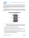
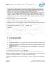
Software inserts receive descriptors by advancing the tail pointer(s) to refer to the address of the entry
just beyond the last valid descriptor. This is accomplished by writing the descriptor tail register(s) with
the offset of the entry beyond the last valid descriptor. Hardware adjusts its internal tail pointer(s)
accordingly. As packets arrive, they are stored in memory and the head pointer(s) is incremented by
hardware. When the head pointer(s) is equal to the tail pointer(s), the queue(s) is empty. Hardware
stops storing packets in system memory until software advances the tail pointer(s), making more
receive buffers available.
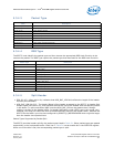
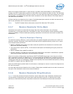
The receive descriptor head and tail pointers reference to16-byte blocks of memory. Shaded boxes in
the figure represent descriptors that have stored incoming packets but have not yet been recognized by
software. Software can determine if a receive buffer is valid by reading the descriptors in memory. Any
descriptor with a non-zero status byte has been processed by the hardware, and is ready to be handled
by the software.
Figure 3. Receive Descriptor Ring Structure
Note: The head pointer points to the next descriptor that is written back. At the completion of the
descriptor write-back operation, this pointer is incremented by the number of descriptors
written back. HARDWARE OWNS ALL DESCRIPTORS BETWEEN [HEAD AND TAIL].
Any descriptor not in this range is owned by software.
The receive descriptor ring is described by the following registers:
• Receive Descriptor Base Address registers (RDBA0, RDBA1, RDBA2, RDBA3)
These registers indicate the state of the descriptor ring buffer. This 64-bit address is aligned on a
16-byte boundary and is stored in two consecutive 32-bit registers. Hardware ignores the lower 4
bits.
• Receive Descriptor Length registers (RDLEN0, RDLEN1, RDLEN2, RDLEN3)
These registers determine the number of bytes allocated to the circular buffer. This value must be a
multiple of 128 (the maximum cache line size). Since each descriptor is 16 bytes in length, the total
number of receive descriptors is always a multiple of 8.
• Receive Descriptor Head registers (RDH0, RDH1, RDH2, RDH3)
Circular Buffer Queues
Head
Base + Size
Base
Receive
Queue
Tail
Owned By
Hardware