PHY Registers — Intel
®
82575EB Gigabit Ethernet Controller
324632-003 Intel
®
82575EB Gigabit Ethernet Controller
Revision: 2.1 Software Developer’s Manual and EEPROM Guide
January 2011 321
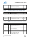
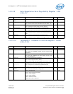
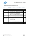
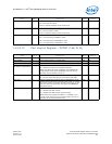
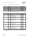
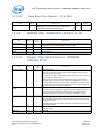
14.3.8.15 Port Control Register - PCONT (18d; R/W)
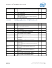
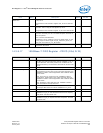
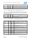
Receive Status 12 1b = PHY currently receiving a packet.
0b = PHY receiver is IDLE.
When in internal loopback, this bit reads as 0b.
RO 0b
Transmit Status 13 1b = PHY currently transmitting a packet.
0b = PHY transmitter is IDLE.
When in internal loopback, this bit reads as 0b.
RO 00b
Data Rate 15:14 00b = Reserved.
01b = PHY operating in 10BASE-T mode.
10b = PHY operating in 100BASE-TX mode.
11b = PHY operating in 1000BASE-T mode.
RO 0b
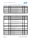
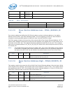
Field Bit(s) Description Mode Default
Reserved 3:0 Always read as 0b. Write to 0b for normal operation. R/W 0b
TP Loopback 4 Allow gigabit loopback on twisted pairs. R/W 0b
Reserved 8:5 Always read as 0000b. Write to 0000b for normal operation. R/W 0000b
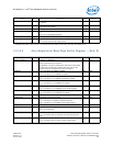
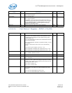
Non-Compliant
Scrambler Compensation
9 1b = Detect and correct for non-compliant scrambler.
0b = Detect and report non-compliant scrambler.
Note: The default of this bit is affected by the EEPROM bit
configurations of the 82575. If EEPROM word 21h, bit 2 is
asserted, then the default is set to 1b.
R/W 0b
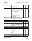
TEN_CRS_Select 10 1b = Extend CRS to cover 1000Base-T latency and RX_DV.
0b = Do not extend CRS (RX_DV can continue past CRS).
R/W 1b
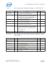
Flip_Chip 11 Used for applications where the core or application is mirror-
imaged. Channel D acts like channel A with t10pol_inv set and
vice-versa. Channel C acts like channel B with t10pol_inv set
and vice-versa. This forces the correctness of all MDI/MDIX
and polarity issues.
R/W 0b
Auto-MDI-X 12 Auto-MDI-X algorithm enable.
1b = Enable Auto-MDI-X mode.
0b = Disable Auto-MDI-X mode (manual mode).
Note: When forcing speed to 10Base-T or 100Base-T, use
manual mode. Clear the bit and set PHY register 18d, bit 13
according to the required MDI-X mode.
R/W 1b
Field Bit(s) Description Mode Default


