


PCI Power Management Registers — Intel
®
82575EB Gigabit Ethernet Controller
324632-003 Intel
®
82575EB Gigabit Ethernet Controller
Revision: 2.1 Software Developer’s Manual and EEPROM Guide
January 2011 197
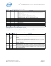
PMCSR_BSE Bridge Support Extensions: 1 Byte, Offset 46h, (RO)
This field is 1 byte at offset 46h and is read only. This register is not implemented in the 82575 and its
value should be set to 00h.
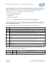
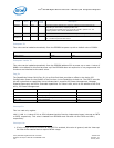
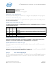
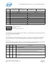
Data Register: 1 Byte, Offset CFh, (RO)
The Data Register is 1 byte at offset CFh and is read only. This optional register is used to report power
consumption and heat dissipation. The reported register is controlled by the Data_Select field in the
PMCSR, and the power scale is reported in the Data_Scale field of the PMCSR. Data from this field is
loaded from the EEPROM if power management is enabled in the EEPROM or with a default value of 00h
otherwise. The values for the 82575 functions are as follows:
Note: For other Data_Select values, the Data Register output is reserved (0b).
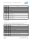
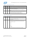
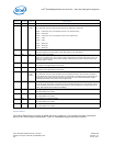
6.6.5.1 Message Signaled Interrupt (MSI) Configuration
Registers
This structure is required for PCIe* devices. There are no changes to this structure from the PCI
Specification, Revision 2.2. Initial values of the configuration registers are marked in parenthesis and
the following color notation is used.
Note: The following color notation is used for reference:
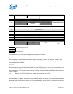
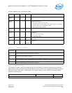
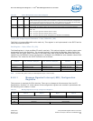
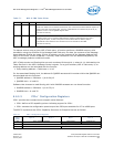
3 0b RO No_Soft_Reset. This bit is always set to 0b to indicate that the 82575 performs an internal reset
while transitioning from D3hot to D0 via software control of the PowerState bits. Configuration
context is lost when performing the soft reset. Upon transition from the D3hot to the D0 state,
full reinitialization sequence is needed to return the 82575 to D0 Initialized.
2 0b RO Reserved for PCIe*.
1:0 00b R/W Power State. This field is used to set and report the power state of a function as defined:
00b – D0
01b – D1 (cycle ignored if written with this value)
10b – D2 (cycle ignored if written with this value)
11b – D3 (cycle ignored if power management is disabled in the EEPROM)
Function D0 (Consume/Dissipate) D3 (Consume/Dissipate) Common
Data
Scale
Data Select 0h / 4h 3h / 7h 8h
Function 0 EEPROM Word 22h EEPROM Word 22h EEPROM Word 22h 01b
Function 1 EEPROM Word 22h EEPROM Word 22h 00h 01b
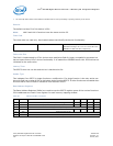
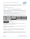
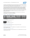
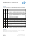
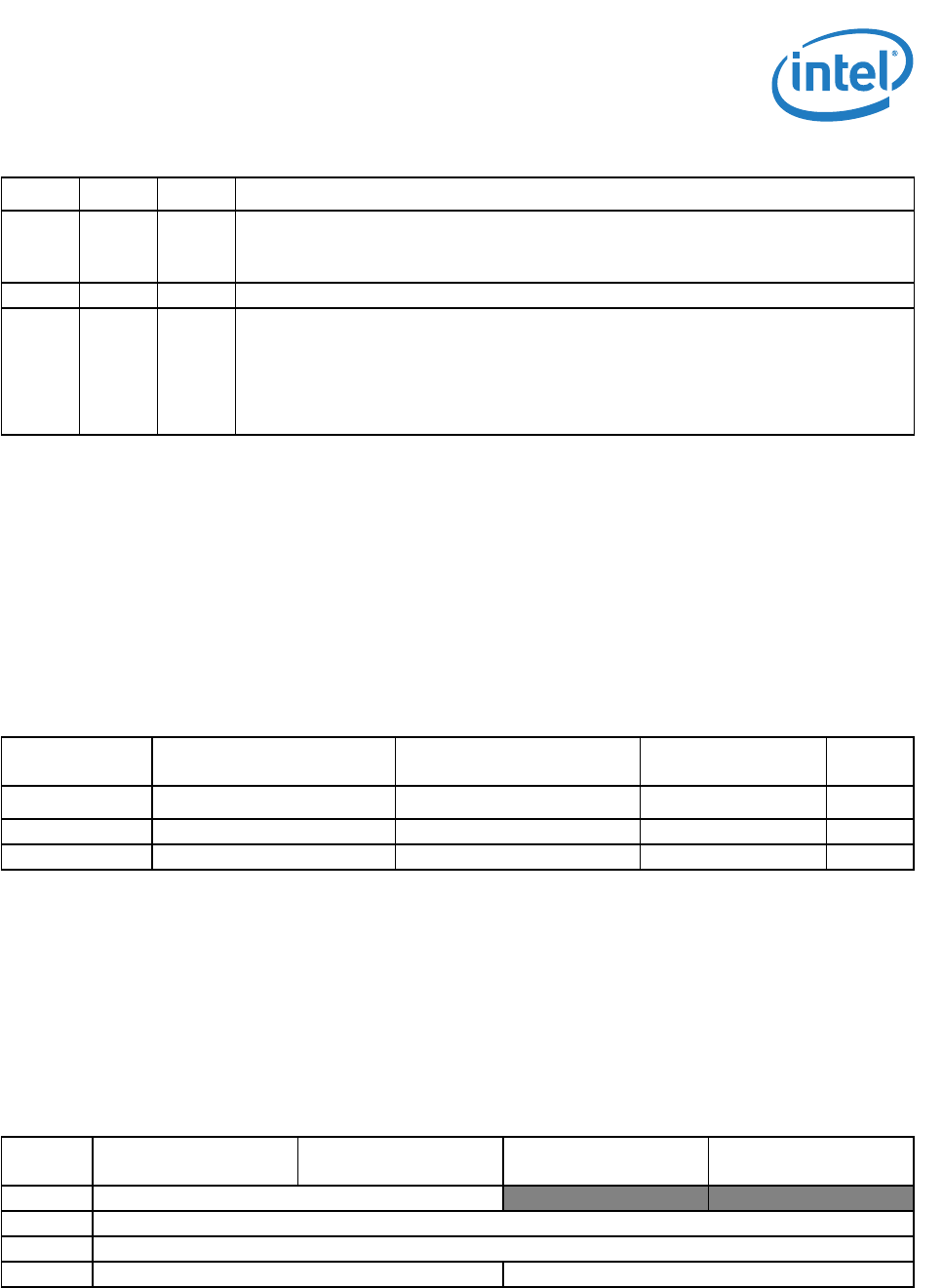
Table 67. Message Signaled Interrupt Configuration Registers
Byte
Offset
Byte 3 Byte 2 Byte 1 Byte 0
50h Message Control (0080h)
Next Pointer (60h) Capability ID (05h)
54h Message Address
58h Message Upper Address
5Ch Reserved Message Data
Table 66. Power Management Control/Status Register
Bit(s) Default RD/WR Description