


Flash Memory Interface — Intel
®
82575EB Gigabit Ethernet Controller
324632-003 Intel
®
82575EB Gigabit Ethernet Controller
Revision: 2.1 Software Developer’s Manual and EEPROM Guide
January 2011 23
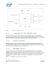
2.1.4 Flash Memory Interface
The 82575 provides an external serial interface to a FLASH device. Accesses to the FLASH are
controlled by the 82575 and are accessible to software as normal PCIe* reads or writes to the FLASH
memory mapping area. The 82575 supports FLASH devices with up to 512 KB of memory
2.1.5 Management Interfaces
The 82575 contains two possible interfaces to an external BMC.
• SMBus
•NC-SI
Since the manageability sideband throughput is lower than the network link throughput, the 82575
allocates an 8 KB internal buffer for incoming network packets prior to being send over the sideband
interface. Refer to the 82575 System Management Bus Interface Application Note for detailed
information about the management interface.
2.1.5.1 Software Watchdog
In some situations it might be useful to give an indication to the manageability firmware or to external
devices that the 82575 hardware or the driver is not functional. In order to provide this functionality, a
watchdog mechanism is used. This mechanism can be enabled by default, according to the EEPROM
configuration. Once the host driver is up and it determines hardware is functional, it might reset the
watchdog timer to indicate the device is functional. The software device driver then should re-arm the
timer periodically. If the timer is not re-armed after a pre-programmed timeout, an interrupt is given to
firmware and a pre-programmed SDP is raised. The SDP indication is shared between the ports.
The register controlling this feature is WDSETUP. This register enables setting the timeout period and
the activation of this mode. Both get their default from the EEPROM.
The re-arming of the timer is done by setting the WDSWSTS.Dev_functional.
If software needs to trigger the watchdog immediately because it suspects hardware is stuck, it can set
the WDSWSTS.Force_WD bit. It can also give firmware an indication if the watchdog reason using the
WDSWSTS.stuck_reason field.
The SDP that provides the watchdog indication is set using the CTRL.SDP0_WDE. In this mode the
CTRL.SDP0_IODIR should be set to output. The CTRL.SDP0_DATA bit indicates the polarity of the
indication. Setting this bit in one of the cores causes the watchdog indications of both cores to be
indicated on this SDP.
2.1.6 General-Purpose I/O (Software-Definable Pins)
The 82575 has four software-defined pins (SDP pins) per port that can be used for miscellaneous
hardware or software-controllable purposes. These pins and their function are bound to a specific LAN
device (for example, eight SDP pins might not be associated with a single LAN device). These pins can
each be individually configurable to act as either input or output pins. The default direction of each of