


Intel
®
82575EB Gigabit Ethernet Controller — PCIe* Counter #2 - GSCN_2 (05B28h; R/W)
Intel
®
82575EB Gigabit Ethernet Controller 324632-003
Software Developer’s Manual and EEPROM Guide Revision: 2.1
408 January 2011
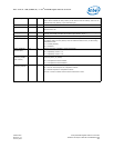
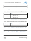
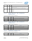
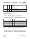
14.8.9 PCIe* Counter #2 - GSCN_2 (05B28h; R/W)
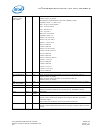
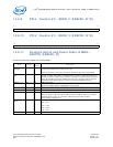
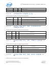
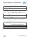
14.8.10 PCIe* Counter #3 - GSCN_3 (05B2Ch; R/W)
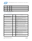
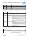
14.8.11 Function Active and Power State to MNG -
FACTPS (05B30h; R)
Firmware uses this register for configuration.
31 0
Event Counter
31 0
Event Counter
Field Bit(s)
Initial
Value
Description
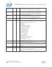
PM State
Changed
31 0b Indication that one or more of the functions power states had changed. This bit is also
a signal to the MNG unit to create an interrupt.
This bit is cleared on read, and is not set for at least 8 cycles after it was cleared.
LAN Function
Sel
30 0b When both LAN ports are enabled and the LAN Function Sel equals 0b, LAN 0 is routed
to PCIe* Function 0 and LAN 1 is routed to PCIe* Function 1. If the LAN Function Sel
equals 1b, LAN 0 is routed to PCIe* Function 1 and LAN 1 is routed to PCIe* Function 0.
If any of the LAN functions are disabled, the other one is routed to PCIe* Function 0
regardless of the LAN Function Sel. This bit is initiated by EEPROM word 21h.
MNGCG 29 0b MNG Clock Gated
When set, indicates that the manageability clock is gated.
Reserved 28:10 0h Reserved
Func1 Aux_En 9 0b Function 1 Auxiliary (AUX) Power PM Enable bit shadow from the configuration space.
LAN1 Valid 8 0b LAN 1 Enable
When set to 0b, it indicates that the LAN 0 function is disabled. When the function is
enabled, the bit is set to 1b. The LAN 0 enable is set by the LAN 1 Enable /
TEST_POINT[3] strapping pin.
Func1 Power
State
7:6 00b Power state indication of Function 1
00b -> DR
01b -> D0u
10b -> D0a
11b -> D3
Reserved 5:4 0b Reserved.