


I/O-Mapped Internal Register, Internal Memory, and Flash — Intel
®
82575EB Gigabit Ethernet
Controller
324632-003 Intel
®
82575EB Gigabit Ethernet Controller
Revision: 2.1 Software Developer’s Manual and EEPROM Guide
January 2011 291
14.1.2.2 IODATA
The IODATA register must always be written as a DWORD access when the IOADDR register contains a
value for the Internal Register and Memories (00000h - 1FFFCh). In this case, writes less than 32 bits
are ignored.
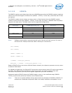
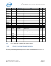
The IODATA register can be written as a byte, word, or Dword access when the IOADDR register
contains a value for the Flash (80000h - FFFFFh). In this case, the value in IOADDR must be properly
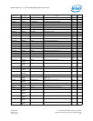
aligned to the data value. The table below lists the supported configurations:
Note: Software might need to implement special code to access the Flash memory at a byte or
word at a time. Example code that reads a Flash byte is shown here:
char *IOADDR;
char *IODATA;
IOADDR = IOBASE + 0;
IODATA = IOBASE + 4;
*(IOADDR) = Flash_Byte_Address;
Read_Data = *(IODATA + (Flash_Byte_Address % 4));
Reads to IODATA of any size returns a Dword of data. However, the chipset or processor can only return
a subset of that Dword.
For software programmers, the IN and OUT instructions must be used to cause I/O cycles to be used on
the PCIe* bus. Where 32-bit quantities are required on writes, the source register of the OUT
instruction must be EAX (the only 32-bit register supported by the OUT command).
Writes and reads to IODATA when the IOADDR register value is in an undefined range (20000h -
7FFFCh) should not be performed. Results can be indeterminate.
Note: There are no special software timing requirements on accesses to IOADDR or IODATA. All
accesses are immediate except when data is not readily available or acceptable. In this
Access Type IOADDR Register Bits [1:0]
Target IODATA Access BE[3:0]# Bits in
Data Phase
BYTE (8 bits) 00b 1110b
01b 1101b
10b 1011b
11b 0111b
WORD (16 bits) 00b 1100b
10b 0011b
DWORD (32 bits) 00b 0000b