


Intel
®
82575EB Gigabit Ethernet Controller — LEDs
Intel
®
82575EB Gigabit Ethernet Controller 324632-003
Software Developer’s Manual and EEPROM Guide Revision: 2.1
24 January 2011
the four pins is configurable via EEPROM as well as the default value of any pins configured as outputs.
To avoid signal contention, all four pins are set as input pins until after the EEPROM configuration is
loaded.
The use, direction, and values of SDP pins are controlled and accessed using fields in the Device Control
register (CTRL) and Extended Device Control register (CTRL_EXT).
2.1.7 LEDs
The 82575 provides four LEDs per port that can be used to indicate different traffic status. The default
setup of the LEDs is done via the EEPROM words 1Ch and 1Fh. The default setup for both ports is the
same. This setup is reflected in the LEDCTL register of each port. Each software device driver can
change its setup individually. For each of the LEDs the following parameters can be defined:
• Mode: Defines which information is reflected by this LED. The encoding is described in the LEDCTL
register.
• Polarity: Defines the polarity of the LED.
• Blink mode: should the LED blink or be stable.
In addition, the blink rate of all LEDs can be defined. The possible rates are 200 ms or 83 ms for each
phase. There is one rate for all LEDs.
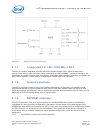
2.1.8 Network Interfaces
The 82575 MAC provides a complete CSMA/CD function that supports IEEE 802.3
(10 Mb/s), 802.3u (100 Mb/s), 802.3z and 802.3ab (1000 Mb/s) implementations. The 82575 performs
all of the functions required for transmission, reception, and collision handling called out in the
standards.
Each 82575 MAC can be configured to be used as a different media interface. While the most likely
application is expected to be based on use of the internal copper PHY, the 82575 supports the following
potential configurations:
• Internal copper PHY
• External SerDes device such as an optical SerDes (SFP or onboard) or backplane connections.
• External SGMII device. This mode is used for SFP connections or external SGMII PHYs.
Selection between the various configurations is programmable via each MAC's Extended Device Control
register (CTRL_EXT.LINK_MODE bits) and defaulted via EEPROM settings.
2.2 DMA Addressing
In appropriate systems, all addresses mastered by the 82575 are 64 bits in order to support systems
that have larger than 32-bit physical addressing. Providing 64-bit addresses eliminates the need for
special segment registers.
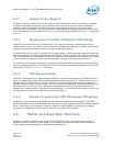
Note: Descriptor accesses are not byte swapped.
The following example illustrates data-byte ordering. Bytes for a receive packet arrive in the order
shown from left to right.