


PHY Registers — Intel
®
82575EB Gigabit Ethernet Controller
324632-003 Intel
®
82575EB Gigabit Ethernet Controller
Revision: 2.1 Software Developer’s Manual and EEPROM Guide
January 2011 311
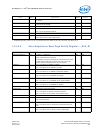
Note: After a PHY reset, access through the MDIC register should not be attempted for
300 s.
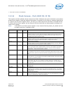
14.3.8 PHY Registers
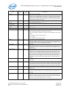
This document uses a special nomenclature to define the read/write mode of individual bits in each
register. See Table 89.
For all binary equations appearing in the register map, the symbol “|” is equivalent to a binary OR
operation.
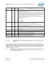
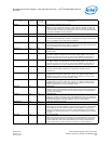
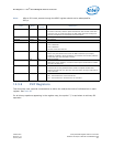
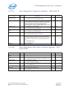
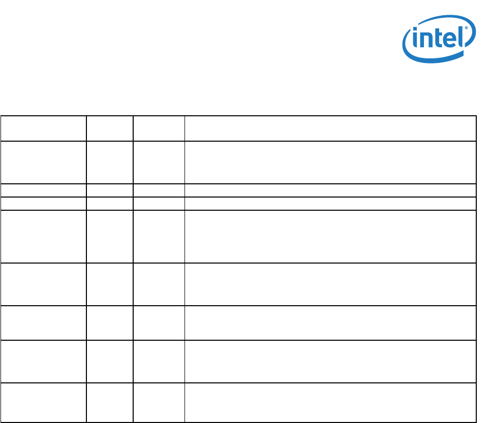
Field Bit(s)
Initial
Value
Description
DATA 15:0 X Data
In a Write command, software places the data bits and the MAC shifts them
out to the PHY. In a Read command, the MAC reads these bits serially from
the PHY and software can read them from this location.
REGADD 20:16 0b PHY Register Address: Reg. 0, 1, 2, ...31
PHYADD 25:21 0b PHY Address
OP 27:26 0b Opcode
01b = MDI Write
10b = MDI Read
All other values are reserved.
R (RWS) 28 0b Ready Bit
Set to 1b by the 82575 at the end of the MDI transaction (for example,
indication of a Read or Write completion). It should be reset to 0b by software
at the same time the command is written.
I 29 0b Interrupt Enable
When set to 1b by software, it causes an Interrupt to be asserted to indicate
the end of an MDI cycle.
E (RWS) 30 0b Error
This bit is set to 1b by hardware when it fails to complete an MDI read.
Software should make sure this bit is clear (0b) before issuing an MDI read or
write command.
Destination 31 0b Destination
0b = The transaction is to the internal PHY.
1b = The transaction is directed to the I
2
C Interface.