


PCI Power Management Registers — Intel
®
82575EB Gigabit Ethernet Controller
324632-003 Intel
®
82575EB Gigabit Ethernet Controller
Revision: 2.1 Software Developer’s Manual and EEPROM Guide
January 2011 205
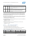
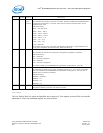
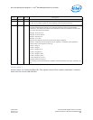
Link CAP
The Link CAP is 4 bytes at offset ACh and is read only. This register identifies the PCIe* Link specific
capabilities. This is a read only register identical to all functions.
Bit(s) RD/WR Default Description
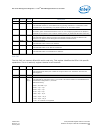
15:6 RO 00h Reserved
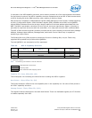
5 RO 0b Transaction Pending
This indicates whether or not the 82575 has any pending transactions. Transactions include
completions for any outstanding non-posted request for all used traffic classes.
4 RO 0b Aux Power Detected
If auxiliary power is detected this field is set to 1b. It is a strapping signal from the periphery
identical for all functions. This is reset on Internal_Power_On_Reset and GIO Power Good only.
3 RW1C 0b Unsupported Request Detected
This indicates that the 82575 received an unsupported request. This field is identical in all
functions. The 82575 cannot distinguish which function caused the error.
2 RW1C 0b Fatal Error Detected
This indicates status of fatal error detection.
1 RW1C 0b Non-Fatal Error Detected
This indicates status of non-fatal error detection.
0 RW1C 0b Correctable Detected
This indicates status of correctable error detection.
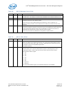
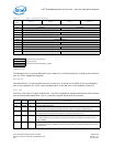
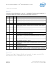
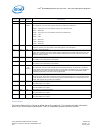
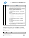
Bit(s) RD/WR Default Description
31:24 HwInit 0b Port Number
This represents the PCIe* port number for the given PCIe* Link. The field is set in the link
training phase.
23:18 RO 0h Reserved
17:15 RO 110b
(32 –
64 μs)
L1 Exit Latency
This indicates the exit latency from L1 to L0 state. This field is loaded from the EEPROM PCIe*
Initialization Configuration 1, word 18h.
Defined encoding:
000b = Less than 1 μs
001b = 1 μs - 2 μs
010b = 2 μs - 4 μs
011b = 4 μs - 8 μs
100b = 8 μs - 16 μs
101b = 16 μs - 32 μs
110b = 32 μs - 64 μs
111b = L1 transition not supported