Hardware Accessed Words — Intel
®
82575EB Gigabit Ethernet Controller
324632-003 Intel
®
82575EB Gigabit Ethernet Controller
Revision: 2.1 Software Developer’s Manual and EEPROM Guide
January 2011 63
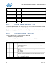
The description of bits 13 and 11 in various combinations are as follows:
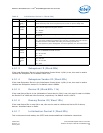
4.5.1.11 NC-SI and PCIe* Completion Timeout Configuration
(Word 15h)
Flash Disable (Bit 13) Boot Disable (Bit 11) Functionality (Active Windows)
0b 0b Flash and Expansion ROM Bars are active.
0b 1b Flash BAR is enabled and Expansion ROM BAR is disabled.
1b 0b Flash BAR is disabled and Expansion ROM BAR is enabled.
1b 1b Flash and Expansion ROM BARs are disabled.
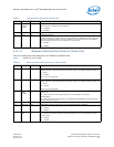
Table 11. NC-SI and PCIe* Completion Timeout Configuration (Word 15h)
Bit(s) Name Default Description
15 NC-SI
Clock
Pad
Drive
Strength
0b Defines the driving strength of the NC-SI_CLK_OUT pad.
14 NC-SI
Data Pad
Drive
Strength
0b Defines the drive strength of the NC-SI_DV & NC-SI_RXD pads.
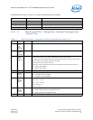
13 NC-SI
Output
Clock
Disable
0b If set, the clock source is external. In this case, the NC-SI_CLK_OUT pad is kept stable at
zero and the NC-SI_CLK_IN pad is used as an input source of the clock.
If cleared, the 82575 outputs the NC-SI clock through the NC-SI_CLK_OUT pad. The NC-
SI_CLK_IN pad is still used as an NC-SI clock input.
If NC-SI is not used, then this bit is set.
If this bit is cleared, the Device Dr Power Down Enable in word 0Fh should not be set.
0b = Output clock enabled.
1b = Output clock enable.
12:8 Reserved - Reserved.
7 Com-
pletion
Timeout
Disable
0b This bit is loaded into the GCR.Completion_Timeout_Disable bit.
0b = Completion timeout enabled.
1b = Completion timeout disabled.
6:5 Com-
pletion
Timeout
Value
00b These bits are loaded into the GCR.Completion_Timeout_Value bit.
00b = 50 s - 10 ms.
01b = 10 ms - 200 ms.
10b = 200 ms - 4 s.
11b = 4 s - 64 s.
4 Com-
pletion
Timeout
Resend
1b This bit is loaded into the GCR.Completion_Timeout_Resend bit.
0b = Do not resend request on completion timeout.
1b = Resend request on completion timeout.
3:0 Reserved 0000b Reserved.


