


Intel
®
82575EB Gigabit Ethernet Controller — Parallel Detection
Intel
®
82575EB Gigabit Ethernet Controller 324632-003
Software Developer’s Manual and EEPROM Guide Revision: 2.1
266 January 2011
11.2.4 Parallel Detection
Parallel detection can only be used to establish 10 and 100 links. It occurs when the PHY tries to
negotiate (transmit FLPs to its link partner), but instead of sensing FLPs from the link partner, it senses
100BASE-TX MLT3 code or 10BASE-T Normal Link Pulses (NLPs) instead. In this case, the PHY
immediately stops Auto-Negotiation (terminates transmission of FLPs) and immediately brings up
whatever link corresponds to what it has sensed (MLT3 or NLPs). If the PHY senses both of the
technologies together, a parallel detection fault is detected and the PHY continues sending FLPs
With parallel detection, it is impossible to determine the true duplex state of the link partner, and the
IEEE standard requires the PHY to assume a half-duplex link. Parallel detection also does not allow
exchange of flow-control ability (PAUSE and ASM_DIR) or Master/Slave relationship required by
1000BASE-T. For this reason, parallel detection cannot be used to establish Gigabit Ethernet links.
11.2.5 Auto Cross-Over
Twisted pair Ethernet PHY's must be correctly configured for MDI or MDI-X operation to interoperate.
The PHY supports the automatic MDI/MDI-X configuration originally developed for 1000Base-T and
standardized in IEEE 802.3u section 40. Manual (non-automatic) configuration is still possible.
For 1000BASE-T links, pair identification is determined automatically in accordance with the standard.
For 10/100 links and during auto-negotiation, pair usage is determined by bits 12 and 13 in the PHY
Port Control Register (18d).
In addition, the PHY has an Automatic Crossover Detection function. If bit 12 in PHY register 18d = 1b,
the PHY automatically detects which application is being used and configures itself accordingly.
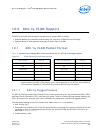
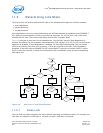
11.2.5.1 Support for Different Board Layouts
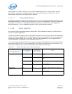
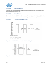
In order to support different board layouts, the 82575 supports an internal flip of the lanes.
The following table lists the logical assignment of the physical lanes in each mode:
The default mode is non-flip chip and auto-MDI-X. For example, MDI or MDI-X mode is set during the
auto-negotiation process (as described in IEEE 802.3, section 40.4.4 Automatic MDI/MDI-X
Configuration).
Flip Chip Non-Flip Chip
MDI Mode A d
B c
C b
D a
A a
B b
C c
D d
MDI-X Mode A c
B d
C a
D b
A b
B a
C d
D c