Intel
®
82575EB Gigabit Ethernet Controller — Hardware Accessed Words
Intel
®
82575EB Gigabit Ethernet Controller 324632-003
Software Developer’s Manual and EEPROM Guide Revision: 2.1
66 January 2011
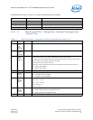
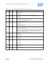
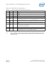
4.5.1.17 PCIe* Initialization Configuration 3 (Word 1Ah)
This word sets default values for some internal registers.
8 SDPDIR[0] 0b SDP0 Pin - Initial Direction. This bit configures the initial hardware value of the
SDP00_IODIR bit in the Device Control (CTRL) register following power up.
0b = Input.
1b = Output.
Set to 1b if not using SDP.
7 SDPVAL[3] 0b This bit holds the value of the SDP3 pin (Initial Output Value). It configures the initial
power-on value output of SDP3 when it is configured as an output. This is accomplished
by configuring the initial hardware value of the SDP3_DATA bit in the Extended Device
Control (CTRL_EXT) register after power up.
6 SDPVAL[2] 0b SDP2 Pin - Initial Output Value. This bit configures the initial power on value output of
SDP2 (when it is configured as an output) by configuring the initial hardware value of the
SDP2_DATA bit in the Extended Device Control (CTRL_EXT) register after power up.
5 WD_SDP0 0b When set, SDP[0] is used as watchdog timeout indication. When reset, it is used as a
Software Defined Pin (as per bits 8 and 0). This bit is mapped to SDP0_WDE[21] in the
CTRL register.
0b = SDP0 is used normally as SDP.
1b = SDP0 is used as a watchdog timeout indication.
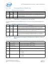
4 Gigabit
Disable
0b When this bit is set, the Gigabit Ethernet operation is disabled. An example of when this
might be used is if Gigabit Ethernet operation exceeds system power limits. Software
configures this bit only if the LAN1/LAN0 OEM Bit configuration disable (word 23h, bits
8:7) are cleared. Hardware does not use this bit.
0b = Enable.
1b = Disable.
3 Disable
1000 in
non-D0a
0b Disables 1000 Mb/s operation in non-D0a states. This bit is for software use. Hardware
does not use this bit.
0b = Enable.
1b = Disable.
2 D3COLD_
WAKEUP_
ADVEN
1b Configures the initial hardware default value of the ADVD3WUC bit in the Device Control
register (CTRL) after power up.
0b = Advertised.
1b = Not advertised.
1 SDPVAL[1] 0b SDP1 Pin - Initial Output Value. This bit configures the initial power on value output of
SDP2 (when it is configured as an output) by configuring the initial hardware value of the
SDP1_DATA bit in the Device Control (CTRL) register after power up.
0 SDPVAL[0] 0b SDP0 Pin - Initial Output Value. This bit configures the initial power on value output of
SDP2 (when it is configured as an output) by configuring the initial hardware value of the
SDP0_DATA bit in the Device Control (CTRL) register after power up.
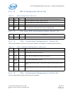
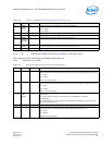
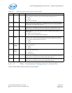
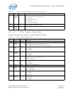
Table 15. Software Defined Pins Control (Word 20h)
Bit(s) Name Default Description


