


Intel
®
82575EB Gigabit Ethernet Controller — Hardware Accessed Words
Intel
®
82575EB Gigabit Ethernet Controller 324632-003
Software Developer’s Manual and EEPROM Guide Revision: 2.1
62 January 2011
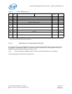
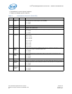
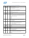
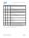
Table 10. Initialization Control 3 (Word 14h and 24h High Byte)
Bit(s) Name Default Description
15 SerDes
Energy
Source
0b SerDes Energy Source Detection
When 0b, internal SerDes Rx electrical Idle indication.
When 1b, external LOS signal.
This bit also indicates the source of the signal detect while establishing a link in SerDes
mode.
This bit sets the default value of the CONNSW.ENRGSRC bit.
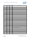
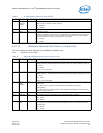
14 I2C SFP
Enable
0b I2C SFP Enable
0b = Disabled. When disabled, the I2C pads are isolated.
1b = Enabled.
Used to set the default value of CTRL_EXT[25].
13 LAN
Flash
Disable
1b A bit value of 1b disables the Flash logic. The Flash access BAR in the PCI Configuration
space is disabled.
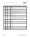
12:11 Interrupt
Pin
0b for LAN
0
1b for LAN
1
This bit controls the value advertised in the Interrupt Pin field of the PCI Configuration
header for this device and function. A value of 0b reflected in the Interrupt Pin field
indicates that this device uses INTA#; a value of 1b indicates that this device uses INTB#.
If only a single port of the 82575 is enabled, this value is ignored and the Interrupt Pin field
of the enabled port reports INTA# usage.
0 = INT#A
1 = INT#B
2 = INT#C
3 = INT#D
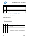
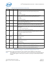
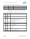
10 APM
Enable
1b This field controls the initial value of Advanced Power Management Wake Up Enable in the
Wake Up Control Register (WUC.APME) and is mapped to CTRL[6] and to WUC[0].
0b = APM wakeup disabled.
1b= =APM wakeup enable.
9:8 Link
Mode
00b This field controls the initial value of Link Mode bits of the Extended Device Control Register
(CTRL_EXT.LINK_MODE), specifying which link interface and protocol is used by the MAC.
00b = MAC operates in 1000Base-T mode with the internal copper PHY.
01b = MAC operates using internal SerDes module (legacy).
10b = MAC operates in SGMII mode.
11b = MAC operates in internal SerDes mode (recommended).
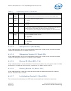
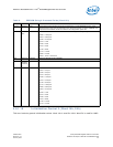
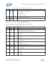
7 Expansio
n BAR
Enable
0b Enable/disable Expansion ROM BAR
0b = Enable.
1b = Disable.
6:5 Reserved - Reserved.
4:2 Reserved 000b Reserved.
1 Ext_VLA
N
0b Sets the default for CTRL_EXT[26] bit. Indicates that additional VLAN is expected in the
system.
1b = Expect additional VLAN in all packets.
0b = Don’t expect additional VLAN.
0 Keep_
PHY_
Link_Up_
En
0b Enables No PHY Reset when the BMC indicates that the PHY should be kept on. When
asserted, this bit prevents the PHY reset signal and the power changes reflected to the PHY
according to the MANC.Keep_PHY_Link_Up value. This bit should be set to the same value
at both words (14h, 24h) to reflect the same option to both LANs.
1b = Enable.
0b = Disable.