


Intel
®
82575EB Gigabit Ethernet Controller — Mandatory PCI Configuration Registers
Intel
®
82575EB Gigabit Ethernet Controller 324632-003
Software Developer’s Manual and EEPROM Guide Revision: 2.1
192 January 2011
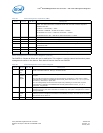
Revision
The default revision ID of this device is 02h.
Note: LAN 0 and LAN 1 functions have the same revision ID.
Class Code
The class code is a read only. Hard coded values that identify the device functionality:
Cache Line Size
This field is implemented by PCIe* devices as a read/write field for legacy compatibility purposes but
has no impact on any PCIe* device functionality. It is loaded from EEPROM words 1Ah. All functions are
initialized to the same value.
Latency Timer
The 82575 does not use this and this bit is hardwired to 0b.
Header Type
This indicates if an 82575 is single function or multifunction. If a single function is the only active one
then this field has a value of 00h to indicate a single function 82575. If other functions are enabled then
this field has a value of 80h to indicate a multi-function 82575.
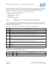
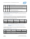
Base Address Registers
The Base Address Registers (BARs) are used to map the 82575 register space of the various functions.
32-bit addresses are used in one register for each memory mapping window.
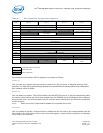
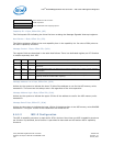
1. The Interrupt Status field is a RO field that indicates that an interrupt message is pending internally to the device.
LAN 0 or LAN 1 020000h/01000h Ethernet/SCSI Adapter
Selected according to bit 11 or 12 in word 1Eh in the
EEPROM for LAN0 and LAN1, respectively.
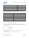
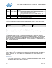
Table 62. LAN 0 and LAN 1 Functions
BAR Address Bits 31:4 Bit 3 Bit 2 Bit 1 Bit 0
0 10h Memory BAR (R/W - 31:17; 0 - 16:4) 0b 0b 0b 0b
1 14h Flash BAR (R/W - 31:23/16; 0 - 22/15:4)
1
1. LAN Flash sizes can be in the range of 64 KB to 8 MB, depending on the Flash size field in EEPROM word 0Fh.
0b 0b 0b 0b
2 18h IO BAR (R/W - 31:5; 0 - 4:1) 0b 1b
3 1Ch MSI-X BAR (R/W - 31:14; '0' - 13:4) 0b 0b 0b 0b
4 20h Reserved (read as 0b)
5 24h Reserved (read as 0b)