


Power Management Interconnects — Intel
®
82575EB Gigabit Ethernet Controller
324632-003 Intel
®
82575EB Gigabit Ethernet Controller
Revision: 2.1 Software Developer’s Manual and EEPROM Guide
January 2011 217
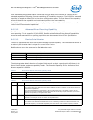
Note: This auxiliary current limit only applies when the primary 3.3V voltage source is not available. For example, the NIC is in a
low power D3 state.
The 82575 exceeds allocated auxiliary power in some configurations (for example, both ports running
at gigabit speed). as a result, the 82575 must be configured such that it meets the previously stated
requirements. To do so, the 82575 implements two EEPROM bits to disable operation in certain cases:
1. The Disable 1000 PHY CSR bit disables 1000 Mb/s operation under all conditions.
2. The Disable 1000 in non-D0a PHY CSR bit disables 1000 Mb/s operation in non-D0a states. If
Disable 1000 in non-D0a is set, and the 82575 is at gigabit speed on entry to a non-D0a state, then
it removes advertisement for 1000 and auto-negotiates.
The 82575 restarts link Auto-Negotiation each time it transitions from a state where gigabit speed is
enabled to a state where gigabit speed is disabled or vice versa. For example, if Disable 1000 Mb/s in
non-D0a is set but Disable 1000 Mb/s is clear, the 82575 restarts link Auto-Negotiation on transition
from the D0 state to D3 or Dr states.
7.4 Power Management Interconnects
This section describes the power reduction techniques employed by 82575 main interconnects.
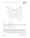
7.4.0.1 PCIe* Link Power Management
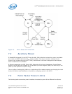
The PCIe* link state follows the power management state of the 82575. Since the 82575 incorporates
multiple PCI functions, the device power management state is defined as the power management state
of the most awake function:
• If any function is in D0 state (either D0a or D0u), the PCIe* link assumes the 82575 is in D0 state.
Else,
• If the functions are in D3 state, the PCIe* link assumes the 82575 is in D3 state. Else,
• The 82575 is in Dr state (PE_RST_N is asserted to all functions).
The 82575 supports all PCIe* power management link states:
• L0 state is used in D0u and D0a states.
• The L0s state is used in D0a and D0u states each time link conditions apply.
• The L1 state is also used in D0a and D0u states when idle conditions apply for a longer period of
time. The L1 state is also used in the D3 state.
• The L2 state is used in the Dr state following a transition from a D3 state if PCI-PM PME is enabled.
• The L3 state is used in the Dr state when no auxiliary power is provided to the 82575.
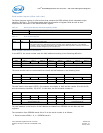
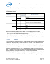
Form Factor
LOM PCIe* NIC
Main N/A 3A @ 3.3v
Auxiliary (aux enabled) 375 mA @ 3.3V 375 mA @ 3.3v
Auxiliary (aux disabled) 20 mA @ 3.3V 20 mA @ 3.3v