Mandatory PCI Configuration Registers — Intel
®
82575EB Gigabit Ethernet Controller
324632-003 Intel
®
82575EB Gigabit Ethernet Controller
Revision: 2.1 Software Developer’s Manual and EEPROM Guide
January 2011 189
The LAN0 and LAN1 are shown in PCI functions 0 and PCI functions 1, respectively. The LAN Function
Select field in EEPROM word 21h is reflected in the FACTPS (05B30h) register and determines if LAN0
appears in PCI function 0 or PCI function 1. LAN1 appears in the complementary PCI function.
All functions contain the following regions of the PCI configuration space:
• Mandatory PCI configuration registers
• Power management capabilities
• MSI capabilities
• PCIe* extended capabilities
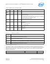
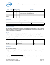
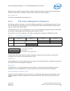
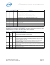
6.6.4 Mandatory PCI Configuration Registers
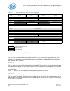
The PCI configuration registers map follows. Registers of the LAN functions that have changed relative
to earlier Gigabit Ethernet controllers are marked in bold italics. Initial values of the configuration
registers are marked in parenthesis.
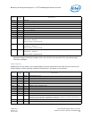
Configuration registers are assigned one of the attributes listed in the following table.
The functions have a separate enabling mechanism. A function that is not enabled does not function
and does not expose its PCI configuration registers.
RD/WR Description
RO Read only register. Register bits are read only and cannot be altered by software.
RW Read/Write register. Register bits are read or write and may be either set or reset.
R/W1C Read only status / Write 1b to Clear register. Writing a 0b to R/W1C bits has no effect.
ROS Read only register with Sticky Bits. Register bits are read only and cannot be altered by software. Bits are not cleared
by reset and can only be reset with the PWRGOOD signal. Devices that consume AUX power are not allowed to reset
sticky bits when AUX power consumption (either through AUX power or PME enable) is enabled.
RWS Read/Write with Sticky Bits: Register bits are read or write and might be either set or reset by software to the desired
state. Bits are not cleared by a reset and can only be reset with the PWRGOOD signal. Devices that consume AUX
power are not allowed to reset sticky bits when AUX power consumption (either through AUX power or PME enable) is
enabled.
R/
W1CS
Read only status / Write 1b to Clear with Sticky Bits. Register bits indicate status when read. A set bit indicates a
status event may be cleared by writing a 1b. Writing a 0b to R/W1C bits has no effect. Bits are not cleared by reset
and can only be reset with the PWRGOOD signal. Devices that consume AUX power are not allowed to reset sticky bits
when AUX power consumption (either through via AUX power or PME enable) is enabled.
HwInit Hardware Initialized. Register bits are initialized by firmware or hardware mechanisms such as pin strapping or serial
EEPROM. Bits are read only after initialization and can only be reset (for write once by firmware) with the PWRGOOD
signal.
RsvdP Reserved and Preserved: This is reserved for future implementations. Software must preserve the value read for
writes to bits.
RsvdZ Reserved and 0b. This is reserved for future R/W1C implementations. Software must use 0b for writes to bits.
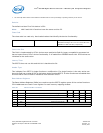
Function Default Initial EEPROM Address
LAN 0 1b Strapping Option.
LAN 1 1b Strapping Option / EEPROM word 10h, bit 11


