Intel
®
82575EB Gigabit Ethernet Controller — PCI Power Management Registers
Intel
®
82575EB Gigabit Ethernet Controller 324632-003
Software Developer’s Manual and EEPROM Guide Revision: 2.1
200 January 2011
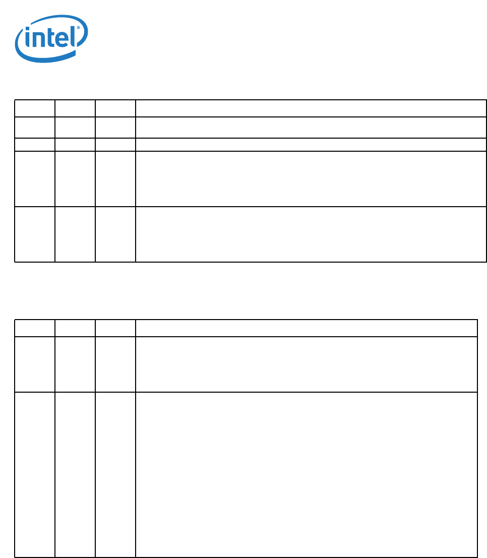
Table 69. MSI-X Message Control Field
Table 70. MSI-X Table Offset
Bits Default RD/WR Description
10:0 009h
1
1. Default is read from the EEPROM.
RO Table Size. System software reads this field to determine the MSI-X Table Size N, which is
encoded as N-1. For example, a returned value of 00000001111b indicates a table size of 16.
13:11 000b RO Always return 0b on reads. Write operation has no effect.
14 0b R/W Function Mask. If set to 1b, all of the vectors associated with the function are masked,
regardless of their per-vector Mask bit states.
If set to 0b, each vector's Mask bit determines whether the vector is masked or not.
Setting or clearing the MSI-X Function Mask bit has no effect on the state of the per-vector
Mask bits.
15 0b R/W MSI-X Enable. If set to 1b and the MSI Enable bit in the MSI Message Control register is 0b, the
function is permitted to use MSI-X to request service and is prohibited from using its INTx# pin.
System configuration software sets this bit to enable MSI-X. A software device driver is
prohibited from writing this bit to mask a function's service request.
If set to 0b, the function is prohibited from using MSI-X to request service.
Bits Default RD/WR Description
31:3 000h RO Table Offset
Used as an offset from the address contained by one of the function's Base Address registers
to point to the base of the MSI-X Table. The lower 3 Table BIR bits are masked off (set to 0b)
by software to form a 32-bit QWORD-aligned offset.
This field is read only.
2:0 3h RO Table BIR
Indicates which one of a function's Base Address registers, located beginning at 10h in
Configuration Space, is used to map the function's MSI-X Table into Memory Space.
BIR Value Base Address register
0 = 10h
1 = 14h
2 = 18h
3 = 1Ch
4 = 20h
5 = 24h
6 = Reserved
7 = Reserved
For a 64-bit Base Address register, the Table BIR indicates the lower DWORD.


