


EEPROM/Flash Control Register - EEC (00010h; R/W) — Intel
®
82575EB Gigabit Ethernet
Controller
324632-003 Intel
®
82575EB Gigabit Ethernet Controller
Revision: 2.1 Software Developer’s Manual and EEPROM Guide
January 2011 303
14.3.3 EEPROM/Flash Control Register - EEC (00010h;
R/W)
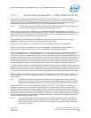
This register provides software direct access to the EEPROM. Software can control the EEPROM by
successive writes to this register. Data and address information is clocked into the EEPROM by software
toggling the EE_SK and EE_DI bits (0 and 2) of this register with EE_CS set to 0b. Data output from the
EEPROM is latched into the EE_DO bit (bit 3) via the internal 62.5 MHz clock and can be accessed by
software via reads of this register.
Note: Attempts to write to the FLASH device when writes are disabled (FWE is not equal to 10b)
should not be attempted. Behavior after such an operation is undefined and can result in
component and/or system hangs.
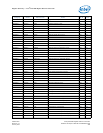
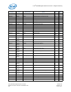
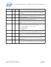
SPEED 7:6 X Link Speed Setting
Reflects the speed setting of the MAC and/or link when it is operating in 10/100/
1000BASE-T mode (internal PHY).
When the MAC is operating in 10/100/1000BASE-T mode with the internal PHY, these
bits normally reflect the speed of the actual link, negotiated by the PHY and link partner
and reflected internally from the PHY to the MAC (SPD_IND). These bits also might
represent the speed configuration of the MAC only, if the MAC speed setting has been
forced via software (CTRL.SPEED) or if MAC auto-speed detection is used.
If Auto-Speed Detection is enabled, the 82575's speed is configured only once after the
LINK signal is asserted by the PHY.
00b = 10 Mb/s.
01b = 100 Mb/s.
10b = 1000 Mb/s.
11b = 1000 Mb/s.
ASDV 9:8 X Auto-Speed Detection Value
Speed result sensed by the 82575’s MAC auto-detection function.
These bits are provided for diagnostics purposes only. The ASD calculation can be
initiated by software writing a logic 1b to the CTRL_EXT.ASDCHK bit. The resultant
speed detection is reflected in these bits.
PHYRA 10 1b PHY Reset Asserted
This read/write bit is set by hardware following the assertion of a PHY reset; it is cleared
by writing a 0b to it. This bit is also used by firmware indicating a required initialization
of the 82575’s PHY.
Reserved 18:11 0h Reserved
GIO Master
Enable Status
19 1b This bit is cleared by the 82575 when the GIO Master Disable bit is set and no master
requests are pending by this function. Indicates that no master requests are issued by
this function as long as the GIO Master Disable bit is set.
Reserved 30:20 0h Reserved
DMA Clock
Gating Enable
31 0b
1
DMA clock gating Enable bit loaded from the EEPROM.
Indicates that the 82575 supports DMA clock gating.
1. If the signature bits of the EEPROM’s Initialization Control Word 1 match (01b), this bit is read from the
EEPROM.
Field Bit(s)
Initial
Value
Description