Hardware Accessed Words — Intel
®
82575EB Gigabit Ethernet Controller
324632-003 Intel
®
82575EB Gigabit Ethernet Controller
Revision: 2.1 Software Developer’s Manual and EEPROM Guide
January 2011 59
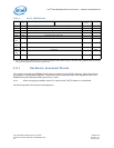
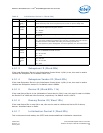
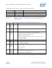
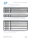
4.5.1.8 Software Defined Pins Control (Word 10h)
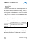
This word configures initial settings for the Software Definable Pins.
Note: Word 10h is for LAN1.
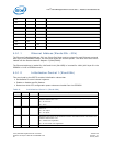
2 SerDesLo
w Power
Enable
0b When this bit is set, the SerDes can enter a low power state when the function is in Dr
state. This bit is mapped to CTRL_EXT[18].
0b = Disabled.
1b = Enabled.
1 Reserved 1b Reserved. Should be set to 0b.
0 LPLU 1b Low Power Link Up
Enables the decrease in link speed in non-D0a states when dictated by power policy and
the power management state. This bit is loaded to each of the PHYs only when LAN0/1
OEM bits disable (word 23 bit 7/8) respectively, are cleared.
0b = Disable.
1b = Enable.
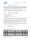
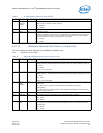
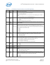
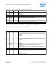
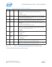
Table 8. Software Defined Pins Control (Word 10h)
Bit(s) Name Default Description
15 SDPDIR[3] 0b SDP3 Pin - Initial Direction. This bit configures the initial hardware value of the
SDP3_IODIR bit in the Extended Device Control (CTRL_EXT) register following power up.
0 = Input.
1b = Output.
Set to 1b if not using SDP.
14 SDPDIR[2] 0b SDP2 Pin - Initial Direction. This bit configures the initial hardware value of the
SDP2_IODIR bit in the Extended Device Control (CTRL_EXT) register following power up.
0 = Input.
1b = Output.
Set to 1b if not using SDP.
13 PHY_in_
LAN_
disable
0b Determines the behavior of the MAC and PHY when a LAN port is disabled through an
external pin.
0b = MAC and PHY maintain functionality while in LAN Disable (to support
manageability).
1b = MAC and PHY are powered down in LAN Disable (manageability cannot access the
network through this port).
12 Reserved 0b Reserved. Should be set to 0b.
11 LAN_DIS 0b LAN Disable. When this bit is set to 1b, the appropriate LAN is disabled.
0b = Enable.
1b = Disable.
10 LAN_PCI_
DIS
0b LAN PCI Disable. When this bit is set to 1b, the appropriate LAN PCI function is disabled.
For example, the LAN is functional for MNG operation but is not connected to the host
through PCIe*.
0b = Enable.
1b = Disable.
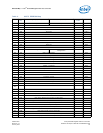
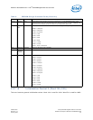
Table 7. Initialization Control 2 (Word 0Fh)
Bit(s) Name Default Description


