


Packet Buffer Allocation - PBA (01000h; R/W) — Intel
®
82575EB Gigabit Ethernet Controller
324632-003 Intel
®
82575EB Gigabit Ethernet Controller
Revision: 2.1 Software Developer’s Manual and EEPROM Guide
January 2011 331
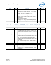
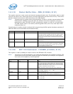
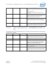
Table 91. Mode Encodings
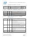
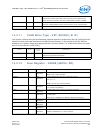
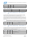
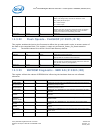
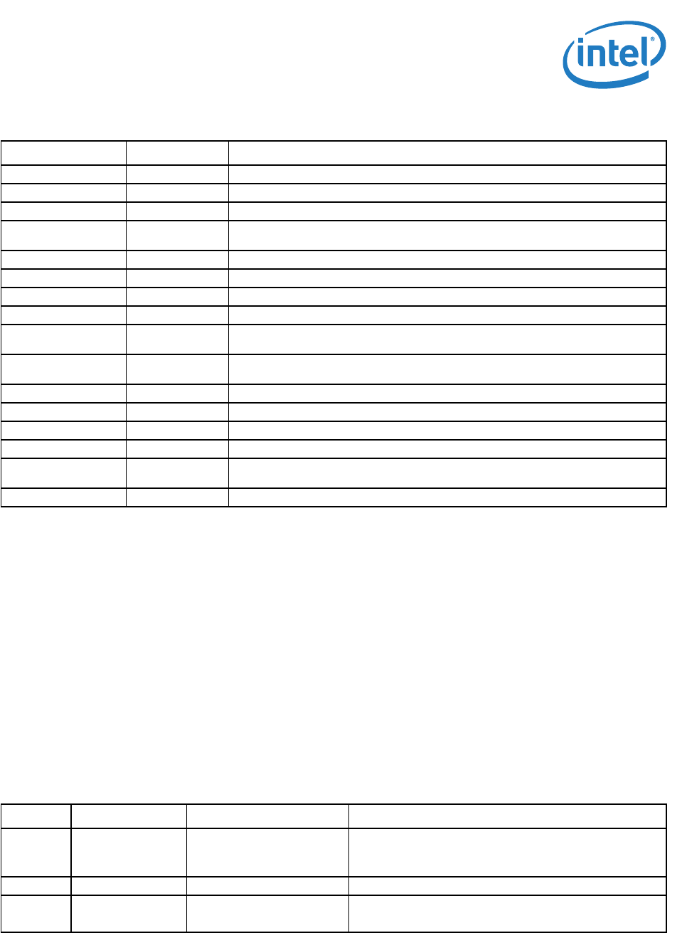
14.3.18 Packet Buffer Allocation - PBA (01000h; R/W)
This register sets the on-chip receive and transmit storage allocation ratio. The receive allocation value
is read/write for the lower six bits. The transmit allocation is read-only and is calculated based on RXA
and CBA. The partitioning size is 1 KB.
Note: Programming this register does not automatically re-load or initialize internal packet-buffer
RAM pointers. Software must reset both transmit and receive operation (using the global
device reset CTRL.RST bit) after changing this register in order for it to take effect. The PBA
register itself is not reset by assertion of the global reset, but is only reset upon initial
hardware power-on.
For best performance, the transmit buffer allocation should be set to accept two full-sized
packets (For good 9 KB jumbo frame performance, the transmit allocation should be a
minimum of
18 KB).
Transmit packet buffer size should be configured to be more than 8 KB.
Mode Selected Mode Source Indication
0000b LINK_10/1000 Asserted when either 10 or 1000 Mb/s link is established and maintained.
0001b LINK_100/1000 Asserted when either 100 or 1000 Mb/s link is established and maintained.
0010b LINK_UP Asserted when any speed link is established and maintained.
0011b FILTER_ACTIVIT
Y
Asserted when link is established and packets are being transmitted or received that
passed MAC filtering.
0100b LINK/ACTIVITY Asserted when link is established and when there is no transmit or receive activity.
0101b LINK_10 Asserted when a 10 Mb/s link is established and maintained.
0110b LINK_100 Asserted when a 100 Mb/s link is established and maintained.
0111b LINK_1000 Asserted when a 1000 Mb/s link is established and maintained.
1000b SDP_MODE LED activation is a reflection of the SDP signal. SDP0, SDP1, SDP2, SDP3 are
reflected to LED0, LED1, LED2, LED3 respectively.
1001b FULL_DUPLEX Asserted when the link is configured for full duplex operation (de-asserted in half-
duplex).
1010b COLLISION Asserted when a collision is observed.
1011b ACTIVITY Asserted when either 10 or 1000 Mb/s link is established and maintained.
1100b BUS_SIZE Asserted when either 100 or 1000 Mb/s link is established and maintained.
1101b PAUSED Asserted when any speed link is established and maintained.
1110b LED_ON Asserted when link is established and packets are being transmitted or received that
passed MAC filtering.
1111b LED_OFF Asserted when link is established and when there is no transmit or receive activity.
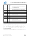
Field Bit(s) Initial Value Description
RXA 9:0 0022h Receive Packet Buffer Allocation in KB
The upper four bits are read only as 0b. Default is
34 KB.
Reserved 15:10 00h Reserved.
TXA (RO) 31:16 000Eh Transmit Packet Buffer Allocation in KB
These bits read only. Default is 14 KB.