


Intel
®
82575EB Gigabit Ethernet Controller — PCI Power Management Registers
Intel
®
82575EB Gigabit Ethernet Controller 324632-003
Software Developer’s Manual and EEPROM Guide Revision: 2.1
202 January 2011
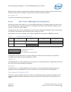
Note: The following color notation is used for reference:
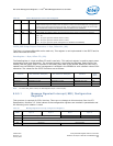
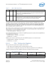
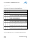
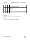
Capability ID
The Capability ID is 1 byte at offset A0h and is read only. This field equals 10h, indicating the linked list
item is a PCIe* Capabilities Register.
Next Pointer
The Next Pointer is 1 byte at offset A1h and is read only. It points to the offset of the next capability
item in the capability list. A 00h value indicates that it is the last item in the capability linked list.
PCIe* CAP
The PCIe* CAP field is 2 bytes at offset A2h. The PCIe* capabilities register identifies the PCIe* device
type and associated capabilities. This is a read only register identical to all functions.
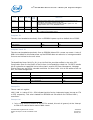
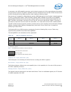
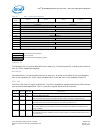
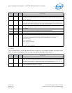
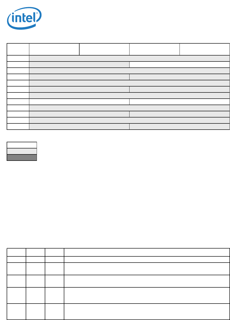
ACh Link Capability
B0h
Link Status Link Control
B4h
Reserved
B8h
Reserved Reserved
BCh
Reserved
C0h
Reserved Reserved
C4h
Device Capability 2
C8h Reserved Device Control
CCh
Reserved
D0h
Reserved Reserved
D4h
Reserved
D8h
Reserved Reserved
Fields identical to all functions.
Read only fields.
Hard coded fields and strapping options.
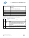
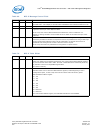
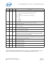
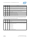
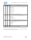
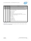
Bit(s) Default RD/WR Description
15:14 00b RO Reserved
13:9 00000b RO Interrupt Message Number
The 82575 does not implement multiple MSI per function. This field is hardwired to 0b.
8 0b RO Slot Implemented
The 82575 does not implement slot options. This field is hardwired to 0b.
7:4 0000b RO Device/Port Type
This field indicates the type of PCIe* functions. All functions are Native PCI functions with a
value of 0000b.
3:0 0001b
1
RO Capability Version
This indicates the PCIe* capability structure version number. The 82575 supports both version
1 and version 2.
Table 72. PCIe* Configuration Registers
Byte
Offset
Byte 3 Byte 2 Byte 1 Byte 0