EEPROM Map Shared Words — Intel
®
82575EB Gigabit Ethernet Controller
324632-003 Intel
®
82575EB Gigabit Ethernet Controller
Revision: 2.1 Software Developer’s Manual and EEPROM Guide
January 2011 51
• Hardware auto read.
• Accesses of port 0 LAN driver.
• Accesses of port 1 LAN driver.
• Firmware accesses.
All clients can access the EEPROM using parallel access, where hardware implements the actual access
to the EEPROM. Hardware can also schedule these accesses so that all clients get served without
starvation.
However, software and firmware clients can access the EEPROM using bit banging. In this case, there is
a request/grant mechanism that locks the EEPROM to the exclusive usage of one client. If this client is
stuck without releasing the lock, the other clients can no longer access the EEPROM. To avoid this, the
82575 implements a timeout mechanism that releases the grant from a client that did not toggle the
EEPROM bit-bang interface for more than two seconds.
Consequently, if an agent that was granted access to the EEPROM for bit-bang access did not toggle,
the bit bang interface for 500 ms. The agent should check if it still owns the interface before continuing
the bit-banging.
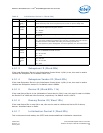
4.3.2 EEPROM Map Shared Words
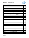
The EEPROM map lists those words configuring either LAN devices or the entire 82575 as LAN 0/LAN 1
Both. Those words configuring a specific LAN’s device parameters are identified as either LAN 0 or LAN
1.
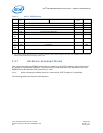
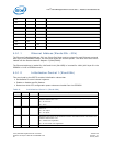
The following EEPROM words warrant additional notes specifically related to dual-LAN support:
4.4 Shared FLASH
The 82575 provides an interface to an external serial Flash/ROM memory device. This Flash/ROM
device can be mapped into memory and/or I/O address space for each LAN device through the use of
Base Address Registers (BARs). Bit 13 of the EEPROM Initialization Control Word 3 associated with each
LAN device selectively disables/enables whether the Flash can be mapped for each LAN device by
controlling the BAR register advertisement and write ability.
Ethernet Address (IA)
(LAN 0/LAN 1 shared)
The EEPROM specifies the IA associated with the LAN 0 device and used as the hardware
default of the Receive Address registers for that device. The hardware-default IA for the
LAN 1 device is automatically determined by the same EEPROM word and is set to the value
of {IA
LAN 0
XOR 010000000000h}.
Initialization Control 1,
Initialization Control 2
(LAN 0/LAN 1 shared)
These EEPROM words specify hardware-default values for parameters that apply a single
value to both LAN devices, such as link configuration parameters required for auto-
negotiation, wakeup settings, PCI/PCI-X bus advertised capabilities, etc.
Initialization Control 3
(LAN 0, LAN 1 unique)
This EEPROM word configures default values associated with each LAN device's hardware
connections, including which link mode (internal PHY) is used with this LAN device. Because
a separate EEPROM word configures the defaults for each LAN, extra care must be taken to
ensure that the EEPROM image does not specify a resource conflict.


