Intel
®
82575EB Gigabit Ethernet Controller — Hardware Accessed Words
Intel
®
82575EB Gigabit Ethernet Controller 324632-003
Software Developer’s Manual and EEPROM Guide Revision: 2.1
58 January 2011
• Set defaults for some internal registers.
• Enable and disable specific features.
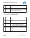
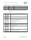
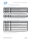
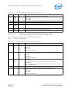
Table 7. Initialization Control 2 (Word 0Fh)
Bit(s) Name Default Description
15 APM PME#
Enable
0b The APM PME# Enable bit represents the initial value of the Assert PME On APM Wakeup
bit in the Wake Up Control Register (WUC.APMPME).
0b = Disable
1b = Enable
14 Reserved 0b Reserved. Should be set to 0b.
13:12 Pause
Capability
11b These bits enable the desired PAUSE capability for the advertised configuration base page.
Mapped to PCS_ANADV.ASM.
11 ANE 0b This bit enables Auto-Negotiation and is mapped to PCS_LCTL.AN_ENABLE.
0b = Disable.
1b = Enable.
10:8 Flash Size
Indication
000b Requested flash Memory Space:
000b = 64 KB
001b = 128 KB
010b = 256 KB
011b = 512 KB
100b = 1 MB
101b = 2 MB
110b = 4 MB
111b = 8 MB
7 DMA Clock
Gating
Enable
1b Enables automatic reduction of DMA and MAC frequency. Mapped to STATUS[31]. This bit
is relevant only if the L1 indication enable is set.
0b = Disable.
1b = Enable.
6 PHY Power
Down
Enable
1b This bit enables the PHY to power down. When it is set, the PHY can enter into a low
power state.
0b = Disable.
1b = Enable.
5 Reserved 0b Reserved.
4 CCM PLL
Shutdown
Enable
0b When set, the CCM PLL can be shut down in low power states when the PHY is in power-
down (link disconnect). When cleared, the CCM PLL is not shut down in a low-power state.
0b = Disable.
1b = Enable.
3 L1
Indication
Enable
0b When set, enables idle indication to the L1 mechanism.
0b = Disable.
1b = Enable.


