PT LAN Configuration Structure — Intel
®
82575EB Gigabit Ethernet Controller
324632-003 Intel
®
82575EB Gigabit Ethernet Controller
Revision: 2.1 Software Developer’s Manual and EEPROM Guide
January 2011 93
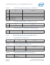
4.6.7.17 LAN0 MAC Value MSB (Offset 2Fh)
4.6.7.18 LAN0 MANC Value LSB (Offset 30h)
4.6.7.19 LAN0 Receive Enable 1(Offset 31h)
4.6.7.20 LAN0 Receive Enable 2 (Offset 32h)
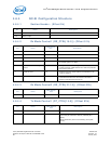
Bit Name Description
15:0 Reserved Reserved.
Bit Name Description
15:9 Reserved Reserved.
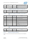
8 Enable IPv4 Address Filters When set, the last 128 bits of the MIPAF register are used
to store four IPv4 addresses for IPv4 filtering. When
cleared, these bits store a single IPv6 filter.
7 Enable Xsum Filtering to MNG When this bit is set, only packets that pass the L3 and L4
checksum are send to the MNG block.
6 Reserved Reserved.
5 Enable MNG Packets to Host
Memory
This bit enables the functionality of the MANC2H register.
When set, the packets that are specified in the MANC2H
registers are also sent to host memory if they pass the
manageability filters.
4:0 Reserved Reserved.
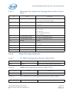
Bit Name Description
15:8 Receive Enable Byte 12 BMC SMBus slave address.
7 Enable BMC Dedicated MAC
6 Reserved Always set to 1b.
5:4 Notification Method 00b = SMBus alert.
01b = Asynchronous notify.
10b = Direct receive.
11b = Reserved.
3 Enable ARP Response
2 Enable Status Reporting
1 Enable Receive All
0 Enable Receive TCO
Bit Name Description
15:8 Receive Enable Byte 14 Alert value.


