


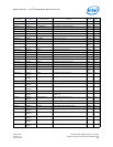
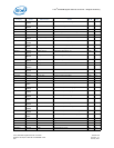
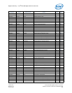
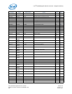

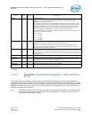

Device Control Register - CTRL (00000h; R/W) — Intel
®
82575EB Gigabit Ethernet Controller
324632-003 Intel
®
82575EB Gigabit Ethernet Controller
Revision: 2.1 Software Developer’s Manual and EEPROM Guide
January 2011 301
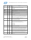
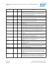
SDP0_GPIEN 16 0b General Purpose Interrupt Detection Enable for SDP0
If software-controlled IO pin SDP0 is configured as an input, this bit (when 1b)
enables the use for GPI interrupt detection.
SDP1_GPIEN 17 0b General Purpose Interrupt Detection Enable for SDP1
If software-controlled IO pin SDP1 is configured as an input, this bit (when 1b)
enables the use for GPI interrupt detection.
SDP0 DATA
(RWS)
18 0b
1
SDP0 Data Value
Used to read or write the value of software-controlled IO pin SDP0. If SDP0 is
configured as an output (SDP0_IODIR = 1b), this bit controls the value driven on
the pin (initial value EEPROM-configurable). If SDP0 is configured as an input, reads
return the current value of the pin.
When the SDP0_WDE bit is set, this field indicates the polarity of the watchdog
indication.
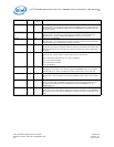
SDP1 DATA
(RWS)
19 0b
1
SDP1 Data Value
Used to read or write the value of software-controlled IO pin SDP1. If SDP1 is
configured as an output (SDP1_IODIR = 1b), this bit controls the value driven on
the pin (initial value EEPROM-configurable). If SDP0 is configured as an input, reads
return the current value of the pin.
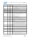
ADVD3WUC 20 1b
1
D3Cold Wakeup Capability Advertisement Enable
When set, D3Cold wakeup capability is advertised based on whether AUX_PWR
advertises presence of auxiliary power (yes if AUX_PWR is indicated, no otherwise).
When 0b, however, D3Cold wakeup capability is not advertised even if AUX_PWR
presence is indicated. Note that the initial value is EEPROM configurable.
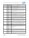
SDP0_WDE 21 0b
1
SDP0 used for Watchdog indication
When set, SDP0 is used as a watchdog indication. When set, the SDP0_DATA bit
indicates the polarity of the watchdog indication. In this mode, SDP0_IODIR must be
set to an output.
SDP0_IODIR 22 0b
1
SDP0 Pin Directionality
Controls whether software-controllable pin SDP0 is configured as an input or output
(0b = input, 1b = output). Initial value is EEPROM-configurable. This bit is not
affected by software or system reset, only by initial power-on or direct software
writes.
SDP1_IODIR 23 0b
1
SDP1 Pin Directionality
Controls whether software-controllable pin SDP1 is configured as an input or output
(0b = input, 1b = output). Initial value is EEPROM-configurable. This bit is not
affected by software or system reset, only by initial power-on or direct software
writes.
Reserved 25:24 0b
1
Reserved. Formerly used as SDP3and SDP2 pin input/output direction control,
respectively.
RST 26 0b Device Reset
This bit performs a reset of the entire 82575, resulting in a state nearly
approximating the state following a power-up reset or internal PCIe* reset, except
for system PCI configuration.
0b = Normal.
1b = Reset.
This bit is self clearing and is referred to as software reset or global reset.
RFCE 27 0b Receive Flow Control Enable
When set, indicates that the 82575 responds to the reception of flow control
packets. Reception of flow control packets requires the correct loading of the FCAL/H
and FCT registers. If Auto-Negotiation is enabled, this bit is set to the negotiated
duplex value.
TFCE 28 0b Transmit Flow Control Enable
When set, indicates that the 82575 transmits flow control packets (XON and XOFF
frames) based on the receiver fullness. If Auto-Negotiation is enabled, this bit is set
to the negotiated duplex value.
Field Bit(s)
Initial
Value
Description