Intel
®
82575EB Gigabit Ethernet Controller — LED Control - LEDCTL (00E00h; RW)
Intel
®
82575EB Gigabit Ethernet Controller 324632-003
Software Developer’s Manual and EEPROM Guide Revision: 2.1
330 January 2011
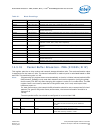
14.3.17.1 MODE Encodings for LED Outputs
Table 91 lists the MODE encodings used to select the desired LED signal source for each LED output.
Note: When LED Blink mode is enabled the appropriate LED Invert bit should be set to 0b.
The dynamic LED modes (FILTER_ACTIVITY, LINK/ACTIVITY, COLLISION, ACTIVITY, PAUSED) should be
used with LED Blink mode enabled.
When LED blink mode is enabled, the blinking frequencies are 1/5 of the rates listed in the Table 91.
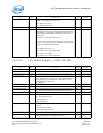
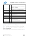
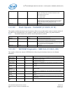
LED0_BLINK 7 0b
1
LED0/LINK# Blink
This field specifies whether to apply blink logic to the (possibly inverted) LED
control source prior to the LED output.
0b = Do not blink asserted LED output.
1b = Blink asserted LED output.
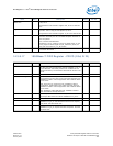
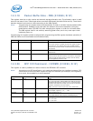
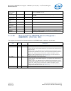
LED1_MODE 11:8 0011b
1
LED1/ACTIVITY# Mode
This field specifies the control source for the LED1 output. An initial value of
0011b selects FILTER ACTIVITY# indication.
Reserved 12 0b Reserved
Read-only as 0b. Write as 0b for future compatibility.
Reserved 13 0b Reserved
LED1_IVRT 14 0b
1
LED1/ACTIVITY# Invert
LED1_BLINK 15 1b
1
LED1/ACTIVITY# Blink
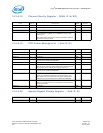
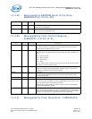
LED2_MODE 19:16 0110b
1
LED2/LINK100# Mode
This field specifies the control source for the LED2 output. An initial value of
0011b selects LINK100# indication.
Reserved 20 0b Reserved
Read-only as 0b. Write as 0b for future compatibility.
Reserved 21 0b Reserved
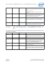
LED2_IVRT 22 0b
1
LED2/LINK100# Invert
LED2_BLINK 23 0b
1
LED2/LINK100# Blink
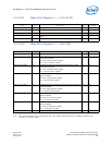
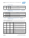
LED3_MODE 27:24 0111b
1
LED3/LINK1000# Mode
This field specifies the control source for the LED3 output. An initial value of
0111b selects LINK1000# indication.
Reserved 28 0b Reserved
Read-only as 0b. Write as 0b for future compatibility.
Reserved 29 0b Reserved
LED3_IVRT 30 0b
1
LED3/LINK1000# Invert
LED3_BLINK 31 0b
1
LED3/LINK1000# Blink
1. These bits are read from the EEPROM.
Field Bit
Initial
Value
Description


