


Intel
®
82575EB Gigabit Ethernet Controller — PCI Power Management Registers
Intel
®
82575EB Gigabit Ethernet Controller 324632-003
Software Developer’s Manual and EEPROM Guide Revision: 2.1
196 January 2011
Power Management Control/Status Register (PMCSR)
The PMCSR is 2 bytes at offset 44h and is read/write. This register is used to control and monitor power
management events in the device. Each device function has its own PMCSR.
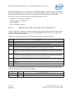
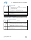
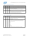
Table 65. Power Management Capabilities (PMC)
Bit(s) Default RD/WR Description
15:11 RO PME_Support. This 5-bit field indicates the power states in which the function may assert
PME#. The IDE function field is hardwired to 0b while the other functions depend on
EEPROM word 0Ah:
Condition Functionality Value
PM Disable in EEPROM No PME at all states 00000b
PM Enable & No Aux Pwr PME at D0 and D3hot 01001b
PM Enable with Aux Pwr PME at D0, D3hot and D3cold 11001b
10 0b RO D2_Support. The 82575 does not support the D2 state.
9 0b RO D1_Support. The 82575 does not support D1 state.
8:6 000b RO Auxiliary Current. This is the required current defined in the data register.
5 1b RO DSI. The 82575 requires its device driver to be executed following transition to the D0
uninitialized state.
4 0b RO Reserved. This bit is reserved and should be set to 0b.
3 0b RO PME_Clock. The PME clock is disabled and is hardwired to 0b.
2:0 010b RO Version. The 82575 complies with PCI Power Management Specification, Revision 1.2.
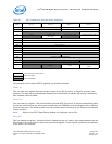
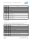
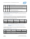
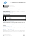
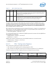
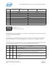
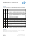
Table 66. Power Management Control/Status Register
Bit(s) Default RD/WR Description
15 0b (at
power
up)
R/W1C PME_Status. This bit is set to 1b when the function detects a wake-up event independent of the
state of the PME enable bit. Writing a 1b clears this bit.
14:13 Reflects
value in
Data
Registe
r
RO Data_Scale. This field indicates the scaling factor that is used to interpret the value of the Data
Register.
For the LAN and Common functions this field equals 01b (indicating 0.1 watt units) if power
management is enabled in the EEPROM and the Data_Select field is set to 0, 3, 4, or 7 (or 8 for
Function 0). Otherwise, it equals 00b.
For the manageability functions this field equals 10b (indicating 0.01 watt units) if power
management is enabled in the EEPROM and the Data_Select field is set to 0, 3, 4, or 7.
Otherwise, it equals 00b.
12:9 0000b R/W Data_Select. This four-bit field is used to select which data is to be reported through the Data
Register and Data_Scale field. These bits are writable only when power management is enabled
through EEPROM.
8 0b (at
power
up)
R/W PME_En. If Power Management is enabled in the EEPROM, writing a 1b to this register enables
wakeup. If power management is disabled in the EEPROM, writing a 1b to this bit has no affect
and will not set the bit to 1b.
7:4 0000b RO Reserved. This bit is reserved and should return a value of 0000b for this field.