


PCI Power Management Registers — Intel
®
82575EB Gigabit Ethernet Controller
324632-003 Intel
®
82575EB Gigabit Ethernet Controller
Revision: 2.1 Software Developer’s Manual and EEPROM Guide
January 2011 203
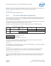
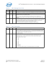
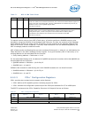
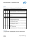
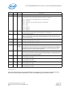
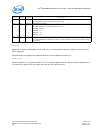
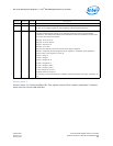
Device CAP
This field is 4 bytes at offset A4h and is read only. It identifies the PCIe* device specific capabilities. It
is a read only register with the same value for LAN function 0 and LAN function 1.
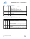
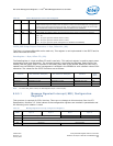
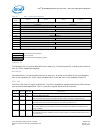
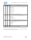
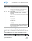
Device Control
The Device Control field is 2 bytes at offset A8h and is read/write. This register controls the PCIe*
specific parameters. There is a dedicated register for each function.
1. Default loaded from the EEPROM.
Bit(s) Default RD/WR Description
31:28 RO 0000b Reserved
27:26 RO 00b Slot Power Limit Scale
This field is used in upstream ports only. It is hardwired in the 82575 to 0b for all functions.
25:18 RO 00h Slot Power Limit Value
This field is used in upstream ports only. It is hardwired in the 82575 to 0b for all functions.
17:16 RO 00b Reserved
15 RO 1b Role-Based Error Reporting
This bit, when set, indicates that the 82575 implements the functionality originally defined in
the Error Reporting ECN for PCIe Base Specification 1.0a and later incorporated into PCIe Base
Specification 1.1.
14 RO 0b Power Indicator Present
In the 82575, this bit is hardwired 0b for all functions.
13 RO 0b Attention Indicator Present
In the 82575, this bit is hardwired 0b for all functions.
12 RO 0b Attention Button Present
In the 82575, this bit is hardwired 0b for all functions.
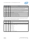
11:9 RO 110b
1
1. Value loaded from the EEPROM
Endpoint L1 Acceptable Latency
This field indicates the acceptable latency that the 82575 can withstand due to the transition
from the L1 state to the L0 state. All functions share the same value loaded from the EEPROM
PCIe* Initialization Configuration 1, word 18h.
8:6 RO 011b
1
Endpoint L0s Acceptable Latency
This field indicates the acceptable latency that the 82575 can withstand due to the transition
from the L0s state to the L0 state. All functions share the same value loaded from the EEPROM
PCIe* Initialization Configuration 1, word 18h.
5 RO 0b Extended Tag Field Supported
This field identifies the maximum Tag field size supported. The 82575 supports a 5-bit Tag field
for all functions.
4:3 RO 00b Phantom Function Supported
This is not supported by the 82575.
2:0 RO 001b
1
Max Payload Size Supported
This field indicates the maximum payload that the 82575 can support for TLPs. It is loaded from
the EEPROM PCIe* Initialization Configuration 3, word 1Ah bit 8, with a default value of 256Bh.