


Intel
®
82575EB Gigabit Ethernet Controller — PCI Power Management Registers
Intel
®
82575EB Gigabit Ethernet Controller 324632-003
Software Developer’s Manual and EEPROM Guide Revision: 2.1
206 January 2011
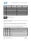
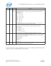
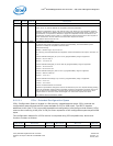
Link Control
The Link Control field is 2 bytes at offset B0h and is read only. This register controls PCIe* link specific
parameters. There is a dedicated register for each function.
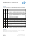
14:12 RO 001b
(64 –
128 ns)
L0s Exit Latency
This indicates the exit latency from L0s to L0 state. This field is loaded from the EEPROM PCIe*
Initialization Configuration 1, word 18h. There are two values for Common PCIe* clock or
Separate PCIe* clock.
Defined encoding:
000b = Less than 64 ns
001b = 64 ns – 128 ns
010b = 128 ns – 256 ns
011b = 256 ns – 512 ns
100b = 512 ns – 1 μs
101b = 1 μs – 2 μs
110b = 2 μs – 4 μs
111b = Reserved
If the 82575 uses common clock, PCIe* Initialization Configuration 1, equals 1B0h/70h, bits
[2:0]; and if the 82575 uses separate clock, 1B0h/70h, bits [5:3].
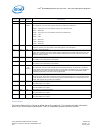
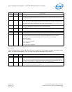
11:10 RO 11b Active State Link PM Support
This indicates the level of active state power management supported in the 82575.
Defined encoding:
00b = Reserved
01b = L0s Entry Supported
10b = Reserved
11b = L0s and L1 Supported
This field is loaded from the EEPROM PCIe* Initialization Configuration 3, word 1Ah.
9:4 RO 4h Max Link Width
This indicates the maximum link width. The 82575 supports by 1-, by 2- and by 4-link width.
The field is loaded from the EEPROM PCIe* Initialization Configuration 3, word 1Ah, with a
default value of 4 lanes for the 82575.
Defined encoding:
000000b = Reserved
000001b = x1
000010b = x2
000100b = x4
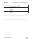
3:0 RO 0001b Max Link Speed
The 82575 indicates a maximum link speed of 2.5 Gb/s.
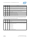
Bit(s) RD/WR Default Description