


Hardware Accessed Words — Intel
®
82575EB Gigabit Ethernet Controller
324632-003 Intel
®
82575EB Gigabit Ethernet Controller
Revision: 2.1 Software Developer’s Manual and EEPROM Guide
January 2011 71
(LINK_UP) and LED2 (LINK_100) output behaviors
Note: A value of 0602h is used to configure default hardware LED behavior equivalent to 82544-
based copper 82575s (LED0=LINK_UP, LED1=blinking ACTIVITY, LED2=LINK_100, and
LED3=LINK_1000).
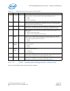
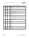
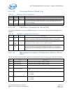
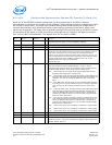
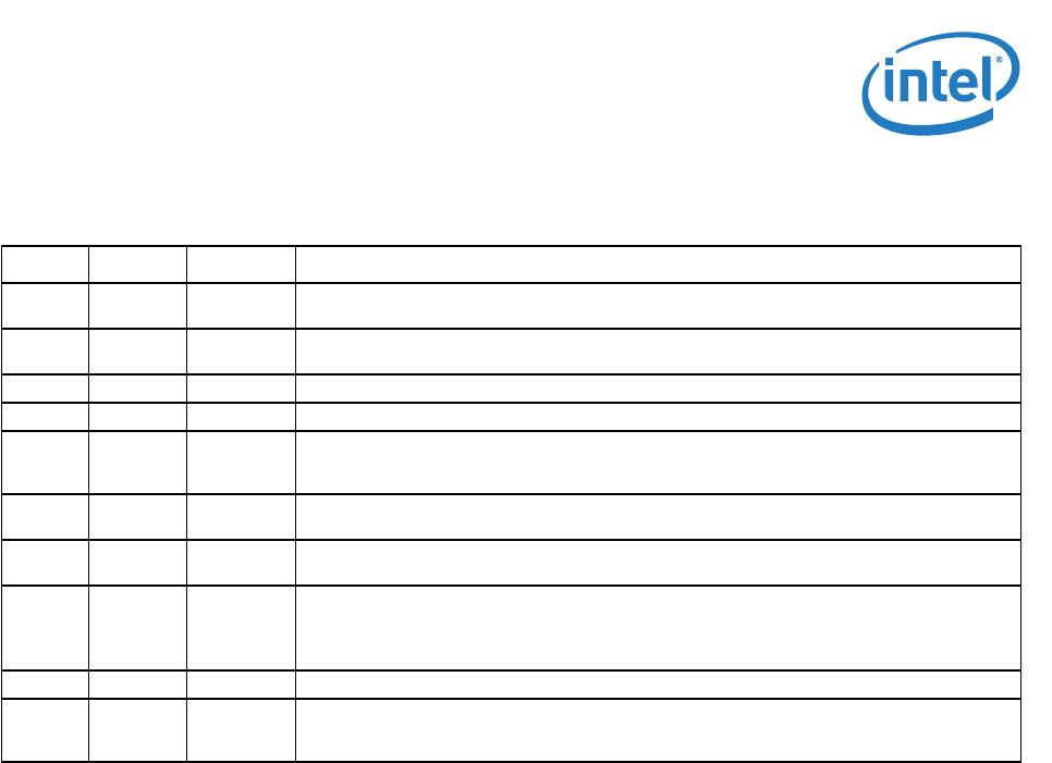
Table 21. LED 0-2 Configuration Defaults (Word 1Fh)
Bit(s) Name Default Description
15 LED2
Blink
0b This bit represents the initial value of the LED2_BLINK field. If it equals 0b, the LED is non-
blinking.
14 LED2
Invert
0b This bit represents the initial value of the LED2_IVRT field. If it equals 0b, it is an active low
output.
13 Reserved 0b
1
1. These bits are read from the EEPROM.
Reserved.
12 Reserved 0b This bit is reserved and should be set to 0b.
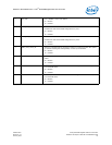
11:8 LED2
Mode
0110b This field represents the initial value of the LED2_MODE specifying the event, state, and
pattern displayed on the LED2 (LINK_1000) output. A value of 0110b (or 6h) causes this to
indicate 100 Mb/s operation. See Table 19 for all available LED modes.
7 LED0
Blink
0b This field holds the initial value of LED0_BLINK field and is equal to 0b for non-blinking.
6 LED0
Invert
0b This field holds the initial value of LED0_IVRT field and is equal to 0b for an active low
output.
5 Global
Blink
Mode
0b
a
Global Blink Mode
0b = Blink at 200 ms on and 200ms off.
1b = Blink at 83 ms on and 83 ms off.
4 Reserved 0b This bit is reserved and should be set to 0b.
3:0 LED0
Mode
0010b This field represents the initial value of the LED0_MODE specifying the event, state, and
pattern displayed on the LED0 (ACTIVITY) output. A value of 0010b (2h) causes this to
indicate link up state. See Table 19 for all available LED modes.