


Intel
®
82575EB Gigabit Ethernet Controller — Testability
Intel
®
82575EB Gigabit Ethernet Controller 324632-003
Software Developer’s Manual and EEPROM Guide Revision: 2.1
450 January 2011
• MAC Loopback while operating with the internal PHY.
• MAC Loopback, by setting the LBM bits in RCTL register to 11b.
• Loopback - 10/100/1000BASE-T PHY: To configure for loopback operation when using internal PHY
mode or 10/100/1000BASE-T mode, the RCTL.LBM should remain configured as for normal
operation (set = 00b). The PHY must be programmed, using MDIO accesses to its MII management
registers, to perform loopback within the PHY.
• Loopback - SerDes: To configure for loopback operation when operating the MAC in SerDes, the
RCTL.LBM should be set =11b. For external SerDes interface operation, this LBM encoding asserts
the EWRAP output pin, which should be connected to the SerDes so as to enable loopback in the
SerDes when asserted.
Note: All loopback modes are only allowed when the 82575 is configured for full duplex operation.
MAC loopback is not functional when the MAC is configured to work at 10 Mb/s.
15.2 Testability
The 82575 uses full Boundary Scan/IEEE 1149.1 JTAG standard test methods. The TAP controller
supports EXTEST, SAMPLE/PRELOAD, IDCODE, and BYPASS instructions.
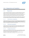
15.2.1 EXTEST Instruction
This instruction allows testing of off-chip circuitry and board level interconnections. Data is typically
loaded onto the latched parallel outputs of the boundary-scan shift register stages using the SAMPLE/
PRELOAD instruction prior to selection of the EXTEST instruction.
15.2.2 SAMPLE/PRELOAD Instruction
In SAMPRE, the boundary scan cells latch values from the 82575 external balls, enabling a programmer
to shift them out through JTAG TDO. Unlike the IEEE standard specification, the 82575 does not support
SAMPLE command and does not enable a snapshot of the normal operation of the component to be
taken and examined. Therefore, in SAMPRE command pads, bidirectional buffers become inputs.
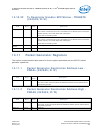
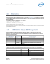
15.2.3 IDCODE Instruction
The IDCODE instruction provides information on the base component. When the 82575 identification
register is included in a component design, the IDCODE instruction is forced into the instruction
register’s parallel output latches.
Note: IDCODE is the default instruction after JTAG FSM is reset.
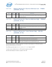
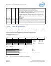
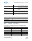
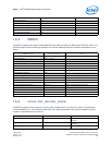
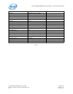
For example, the 82575’s ID is determined and derived from the manufacturer as follows:
Component
Product Code
Ver V Product Gen Model Manf ID 1
ID Code
(hex)
82575 0000 0 001000 0101 01010 00000001001 1 010aa13