


Transmit Descriptor Ring Structure — Intel
®
82575EB Gigabit Ethernet Controller
324632-003 Intel
®
82575EB Gigabit Ethernet Controller
Revision: 2.1 Software Developer’s Manual and EEPROM Guide
January 2011 145
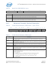
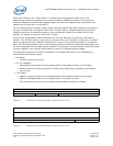
Descriptors passed to hardware should not be manipulated by software until the head pointer has
advanced past them.
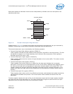
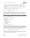
Figure 6. Transmit Descriptor Ring Structure
Shaded boxes in Figure 6 represent descriptors that have been transmitted but not yet reclaimed by
software. Reclaiming involves freeing up buffers associated with the descriptors.
The transmit descriptor ring is described by the following registers:
• Transmit Descriptor Base Address registers (TDBA0-3)
These registers indicate the start address of the descriptor ring buffer in the host memory. This 64-
bit address is aligned on a 16-byte boundary and is stored in two consecutive 32-bit registers.
Hardware ignores the lower 4 bits.
• Transmit Descriptor Length register (TDLEN0-3)
These registers determine the number of bytes allocated to the circular buffer. This value must be
128 byte aligned.
• Transmit Descriptor Head register (TDH0-3)
These registers hold a value which is an offset from the base and indicates the in-progress
descriptor. There can be up to 8 KB descriptors in the circular buffer. Reading these registers return
the value of the head that corresponding to descriptors already loaded in the output FIFO. This
register reflects the internal head of the hardware write-back process including descriptor in the
posted write pipe and might point further ahead than the last descriptor actually written back to
memory.
• Transmit Descriptor Tail register (TDT0-3)
These registers hold a value, which is an offset from the base, and indicates the location beyond the
last descriptor hardware can process. This is the location where software writes the first new
descriptor.
The base register indicates the start of the circular descriptor queue and the length register indicates
the maximum size of the descriptor ring. The lower seven bits of length are hard–wired to 0b. Byte
addresses within the descriptor buffer are computed as follows:
Circular Buffer
Head
Base + Size
Base
Transmit
Queue
Tail
Owned By
Hardware