


Intel
®
82575EB Gigabit Ethernet Controller — Flash Write Control
Intel
®
82575EB Gigabit Ethernet Controller 324632-003
Software Developer’s Manual and EEPROM Guide Revision: 2.1
50 January 2011
To directly access the Flash, software needs to:
1. Write a 1b to the Flash Request bit (FLA.FL_REQ)
2. Read the Flash Grant bit (FLA.FL_GNT) until it = 1b. It remains 0b as long as there are other
accesses to the Flash.
3. Write or read the Flash using the direct access to the 4-wire interface as defined in the Flash Access
register (FLA). The exact protocol used depends on the Flash placed on the board and can be found
in the appropriate datasheet.
4. Write a 0b to the Flash Request bit (FLA.FL_REQ).
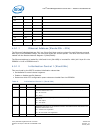
4.2.1 Flash Write Control
The Flash is write controlled by the FWE bits in the EEPROM/FLASH Control and Data register
(EEC.FWE). Note that attempts to write to the Flash device when writes are disabled (FWE = 10b)
should not be attempted. Behavior after such an operation is undefined and can result in component
and/or system hangs.
After sending a one byte write to the Flash, software checks if it can send the next byte to write (check
if the write process in the Flash had finished) by reading the Flash Access register. If the bit
(FLA.FL_BUSY) in this register is set, the current write did not finish. If bit (FLA.FL_BUSY) is cleared,
then software can continue and write the next byte to the Flash.
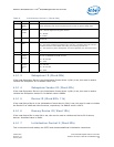
4.2.2 Flash Erase Control
When software needs to erase the Flash, it sets bit FLA.FL_ER in the Flash Access register to 1b (Flash
Erase) and then set bit EEC.FWE in the EEPROM/Flash Control register to 0b.
Hardware gets this command and sends the erase command to the Flash. Note that the erase process
completes automatically. Software should wait for the end of the erase process before any further
access to the Flash. This can be checked by using the Flash Write control mechanism.
The op-code used for erase operation is defined in the FLASHOP register.
Note: Sector erase by software is not supported. In order to delete a sector, the serial (bit bang)
interface should be used.
4.3 Shared EEPROM
The 82575 uses a single EEPROM device to configure hardware default parameters for both LAN devices
including Ethernet Individual Addresses (IA), LED behaviors, receive packet-filters for manageability,
and wakeup capability). Certain EEPROM words are used to specify hardware parameters that are LAN
device-independent (such as those which affect circuits behavior). Other EEPROM words are associated
with a specific LAN device. Both LAN devices access the EEPROM to obtain their respective configuration
settings.
4.3.1 EEPROM Deadlock Avoidance
The EEPROM is a shared resource between four clients: