Ethernet Addressing — Intel
®
82575EB Gigabit Ethernet Controller
324632-003 Intel
®
82575EB Gigabit Ethernet Controller
Revision: 2.1 Software Developer’s Manual and EEPROM Guide
January 2011 25
01 02 03 04 05 06 07 08 09 0a 0b 0c 0d 0e 0f 10 11 12 13 14 15 16 17 18 19 1a 1b 1c 1d 1e
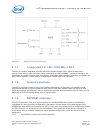
Example 1. Byte Ordering
There are no alignment restrictions on packet-buffer addresses. The byte address for the major words
is shown on the left. The byte numbers and bit numbers for the PCIe* bus are shown across the top.
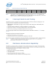
Table 1. Little Endian Data Ordering
2.3 Ethernet Addressing
Several registers store Ethernet addresses in the 82575. Two 32-bit registers make up the address: one
is called “high”, and the other is called “low”. For example, the Receive Address Register is comprised of
Receive Address High (RAH) and Receive Address Low (RAL). The least significant bit of the least
significant byte of the address stored in the register (for example, bit 0 of RAL) is the multicast bit. The
LS byte is the first byte to appear on the wire. This notation applies to all address registers, including
the flow control registers.
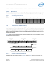
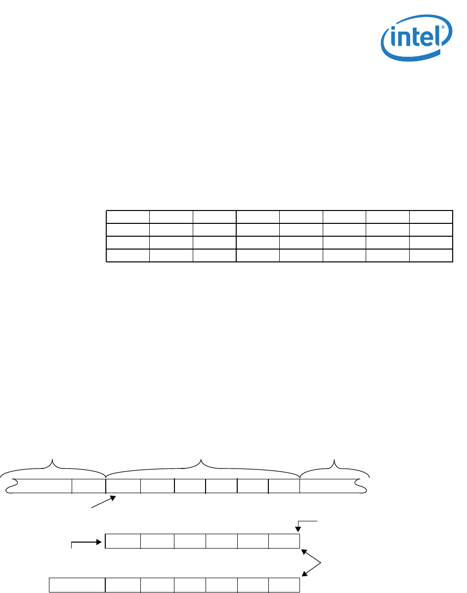
Figure 2 shows the bit/byte addressing order comparison between what is on the wire and the values in
the unique receive address registers.
Figure 2. Example of Address Byte Ordering
The address byte order numbering shown in Figure 2 maps to Table 2. Byte #1 is first on the wire.
Byte
Address
63 0
76543210
00807060504030201
8100f 0e0d0c0b0a09
10 18 17 16 15 14 13 12 11
18 20 1f 1e 1d 1c 1b 1a 19
Preamble & SFD Destination Address Source Address
Bit 0 of this byte is first on the wire
Destination address stored
internally as shown here
dest_addr[0]
Multicast bit
...55 D5 00 11 22 33 ...XXX00 AA
33
...
001122
2233 00AA0011
00AA


