


Hardware Accessed Words — Intel
®
82575EB Gigabit Ethernet Controller
324632-003 Intel
®
82575EB Gigabit Ethernet Controller
Revision: 2.1 Software Developer’s Manual and EEPROM Guide
January 2011 65
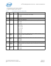
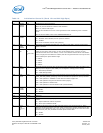
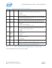
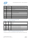
4.5.1.16 Software Defined Pins Control (Word 20h)
This configures initial settings for the Software Definable Pins.
Note: Word 20h is for LAN0.
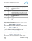
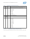
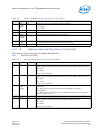
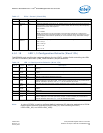
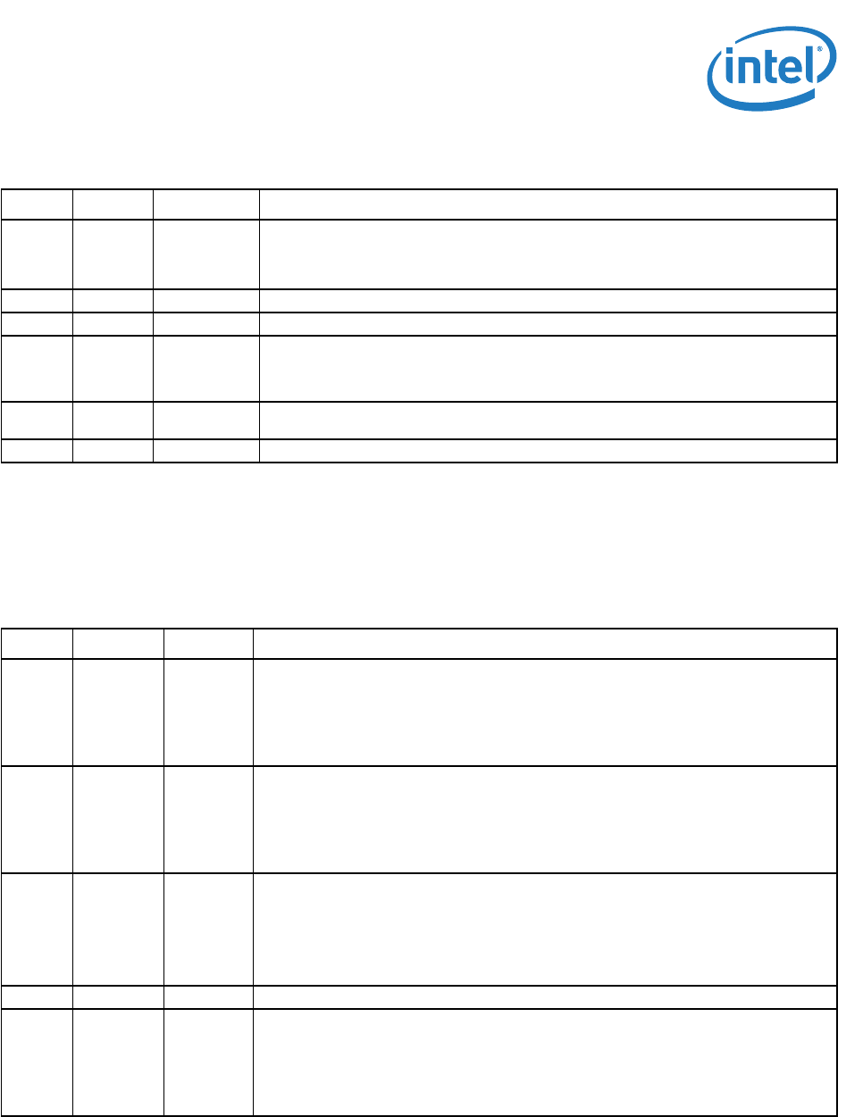
Table 14. PCIe* Initialization Configuration 2 (Word 19h)
Bit(s) Name Default Description
15 DLLP
Timer
Enable
0b When it is set to 1b, the DLLP timer counter is enabled.
0b = Disable.
1b = Enable.
14 Reserved 0b Reserved.
13 Reserved 0b Reserved.
12 Serial
Number
Capabilit
y
1b Serial Number Capability Enable. Should be set to 1b.
11:8 Extra
NFTS
0000b Extra NFTS (Number of Fast Training Signal) that is added to the original requested
number of NFTS (as requested by the upstream component).
7:0 NFTS 50h This field identifies the number of special sequences for L0s transition to L0.
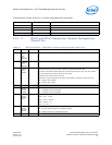
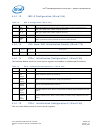
Table 15. Software Defined Pins Control (Word 20h)
Bit(s) Name Default Description
15 SDPDIR[3] 0b SDP3 Pin - Initial Direction. This bit configures the initial hardware value of the
SDP3_IODIR bit in the Extended Device Control (CTRL_EXT) register following power up.
0b = Input.
1b = Output.
Set to 1b if not using SDP.
14 SDPDIR[2] 0b SDP2 Pin - Initial Direction. This bit configures the initial hardware value of the
SDP2_IODIR bit in the Extended Device Control (CTRL_EXT) register following power up.
0b = Input.
1b = Output.
Set to 1b if not using SDP.
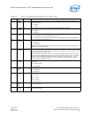
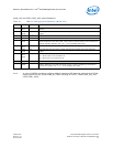
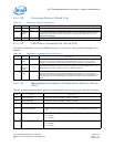
13 PHY_in_
LAN_
disable
0b Determines the behavior of the MAC and PHY when a LAN port is disabled through an
external pin.
0b = MAC and PHY maintain functionality while in LAN Disable (to support
manageability).
1b = MAC and PHY are powered down in LAN Disable (manageability cannot access the
network through this port).
12:10 Reserved 000b Reserved. Should be set to 000b.
9 SDPDIR[1] 0b SDP1 Pin - Initial Direction. This bit configures the initial hardware value of the
SDP1_IODIR bit in the Device Control (CTRL) register following power up.
0b = Input.
1b = Output.
Set to 0b if not using SDP.