


Hardware Accessed Words — Intel
®
82575EB Gigabit Ethernet Controller
324632-003 Intel
®
82575EB Gigabit Ethernet Controller
Revision: 2.1 Software Developer’s Manual and EEPROM Guide
January 2011 69
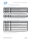
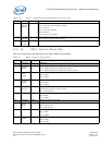
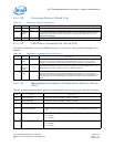
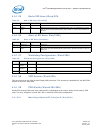
4.5.1.19 LED 1, 3 Configuration Defaults (Word 1Ch)
This EEPROM word specifies the hardware defaults for the LEDCTL register fields controlling the LED1
(ACTIVITY indication) and LED3 (LINK_1000 indication) output behaviors.
Note: A value of 0703h is used to configure default hardware LED behavior equivalent to 82544-
based copper Ethernet controllers (LED0=LINK_UP, LED1=blinking ACTIVITY,
LED2=LINK_100, and LED3=LINK_1000).
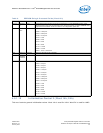
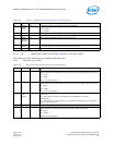
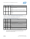
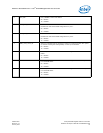
3 Reserved 0b Reserved.
2 Electrical
Idle
0b Electrical Idle Mask. When set to 1b, disables the check for illegal electrical idle sequence
(for example, eidle ordered set without common mode and vise versa). Also excepts any
of them as a correct eidle sequence.
0b = Enable.
1b = Disable
Note: Specification can be interpreted so that the eidle ordered set is sufficient for
transition to power management states. The use of this bit allows an exception for such
interpretation and avoids the possibility of correct behavior being understood as illegal
sequences.
1:0 Latency to
Enter L1
11b These bits identify the period in L0s state before transitioning into an L1 state.
00b = 64 μs
01b = 256 μs
10b = 1 ms
11b = 4 ms
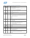
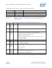
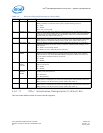
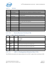
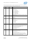
Table 18. LED 1-3 Configuration Defaults (Word 1Ch)
Bit(s) Name Default Description
15 LED3
Blink
0b This bit represents the initial value of the LED3_BLINK field. If it equals 0b, the LED is non-
blinking.
14 LED3
Invert
0b This bit represents the initial value of the LED3_IVRT field. If it equals 0b, it is an active low
output.
13 Reserved 0b
1
1. These bits are read from the EEPROM.
Reserved.
12 Reserved 0b This bit is reserved and should be set to 0b.
11:8 LED3
Mode
0111b This field represents the initial value of the LED3_MODE specifying the event, state, and
pattern displayed on the LED3 (LINK_1000) output. A value of 0111b (or 7h) causes this to
indicate 1000 Mb/s operation. See Table 19 for all available LED modes.
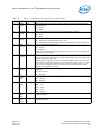
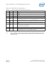
7 LED1
Blink
1b This field holds the initial value of LED1_BLINK field and is equal to 0b for non-blinking.
6 LED1
Invert
0b This field holds the initial value of LED1_IVRT field and is equal to 0b for an active low
output.
5 Reserved 0b
a
Reserved.
4 Reserved 0b This bit is reserved and should be set to 0b.
3:0 LED1
Mode
0011b This field represents the initial value of the LED1_MODE specifying the event, state, and
pattern displayed on the LED1 (ACTIVITY) output. A value of 0011b (3h) causes this to
indicate ACTIVITY state. See Table 19 for all available LED modes.
Table 17. PCIe* Control (Word 1Bh)
Bit(s) Name Default Description