Section 25 Electrical Characteristics
Rev. 4.00 Sep. 14, 2005 Page 963 of 982
REJ09B0023-0400
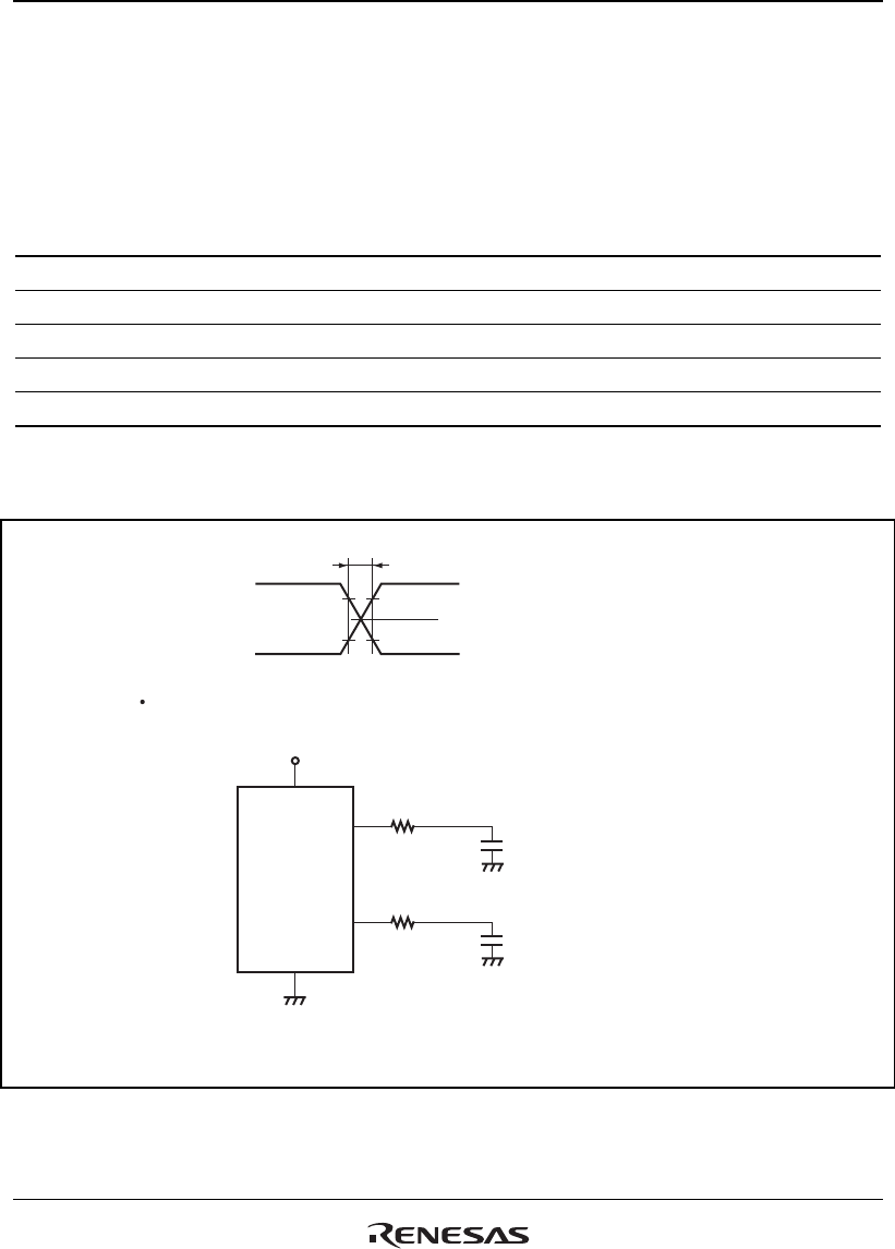
25.3.14 USB Transceiver Timing
Table 25.15 USB Transceiver Timing
Conditions: V
CC
= 1.8 V ±5%, V
CC
Q = 3.0 V to 3.6 V, AV
CC
= 3.0 V to 3.6 V, V
SS
= V
SS
Q = AV
SS
= 0 V, Ta = −40°C to +85°C
Item Symbol Min. Typ. Max. Unit Test Conditions
Rising time t
R
4 20 ns C
L
= 50pF
Falling time t
F
4 — 20 ns C
L
= 50pF
Rising/falling time ratio t
R
/t
F
90 — 110 %
Output crossover voltage V
CRS
1.3 — 2.0 V C
L
= 50pF
Output driver resistance Z
DRU
28 44 Ω
Notes: 1. Transceivers conform to the full-speed specification.
2. The resistance includes the value of the externally connected resistor
(RS = 27 Ω ± 1%).
t
R
, t
F
90%
10%
DP
Crossover voltage
1. The Values of
t
R
and
t
F
are measured at
10%
and
90% of amplitude.
2. The capacitance (
C
L
) includes stray capacitance of writing connection and
probe input capacitance.
Notes:
DM
VccQ
DP
DM
VssQ
R
L
= 27 Ω
C
L
C
L
R
L
= 27 Ω
Device to be
measured
Measurement circuit


