Section 17 Compare Match Timer (CMT)
Rev. 4.00 Sep. 14, 2005 Page 509 of 982
REJ09B0023-0400
Section 17 Compare Match Timer (CMT)
This LSI has an on-chip compare match timer (CMT) consisting of a two-channel 16-bit timer.
The CMT has a16-bit counter, and can generate interrupts at set intervals.
17.1 Features
CMT has the following features.
• Selection of four counter input clocks
Any of four internal clocks (Pφ/4, Pφ/8, Pφ/16, and Pφ/64) can be selected independently
for each channel.
• Selection of DMA transfer request or interrupt request generation on compare match
• When not in use, CMT can be stopped by halting its clock supply to reduce power
consumption.
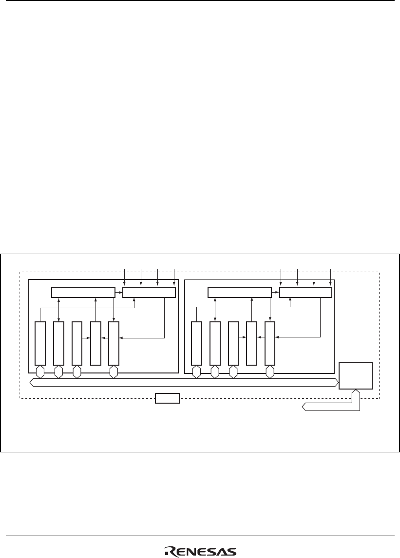
Figure 17.1 shows a block diagram of CMT.
Control circuit Clock selection
CMSTR_0
CMCSR_0
CMCOR_0
CMCNT_0
Channel 0 Channel 1
CMT
Pφ/4
CMSTR_1
CMCSR_1
CMCOR_1
CMCNT_1
Pφ/8
Pφ/16Pφ/64
Pφ/4
Pφ/8
Pφ/16Pφ/64
Clock selectionControl circuit
Comparator
Comparator
CMSTR:
CMCSR:
CMCOR:
CMCNT:
Compare match timer start register
Compare match timer control/status register
Compare match timer constant register
Compare match counter
[Legend]
Module bus
Bus
interface
Internal bus
Figure 17.1 Block Diagram of Compare Match Timer


