


Section 6 Power-Down Modes
Rev. 4.00 Sep. 14, 2005 Page 164 of 982
REJ09B0023-0400
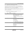
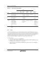
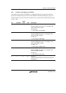
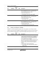
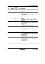
Table 6.1 States of Power-Down Modes
State*
Mode Transition Conditions CPG CPU
CPU
Register
On-Chip
Memory
On-Chip
Peripheral
Modules
External
Memory
Canceling
Procedure
Sleep mode Execute SLEEP
instruction with STBY bit
cleared to 0 in STBCR
Runs Halts Held Halts
(The contents
are retained.)
The UBC stops.
Other modules
continue to run.
Refreshed
automati-cally
1. Interrupt
2. Reset
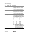
Standby mode Execute SLEEP
instruction with STBY bit
set to 1 in STBCR
Halts Halts Held Halts
(The contents
are retained.)
Halt Self-refreshed 1. Interrupt
2. Reset
Module standby
function
Set the MSTP bits in
STBCR, STBCR2,
STBCR3, and STBCR4
to 1 (with the exception
of the MSTP bits for the
USB module; clear these
bits).
Runs Runs Held The specified
module stops
(the contents are
retained).
Specified
module halts
Refreshed
automati-cally
1. Clear MSTP bit to
0. (with the
exception of the
MSTP bits for the
USB module; set
these bits).
2. Power-on reset
Note: * The pin state is retained or set to high impedance. For details, see Appendix A, Pin
States.
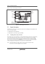
6.1.2 Reset
A reset is used at power-on or to re-execute from the initial state. This LSI supports two types of
reset: power-on reset and manual reset. In power-on reset, any processing to be currently executed
is terminated and any events not executed are canceled to execute reset processing immediately. In
manual reset, processing required to maintain external memory contents is continued. The
following shows the conditions in which power-on reset or manual reset occurs.
• Power-on reset
1. A low level signal is input to the RESETP pin.
2. The WDT counter overflows if WDT starts counting while the WT/IT and RSTS bits of the
WTCSR are set to 1 and cleared to 0, respectively.
3. An H-UDI reset occurs. (For details on H-UDI reset, refer to section 15, User Debugging
Interface (H-UDI).)