


Section 5 Watchdog Timer (WDT)
Rev. 4.00 Sep. 14, 2005 Page 159 of 982
REJ09B0023-0400
5.2.3 Notes on Register Access
The watchdog timer counter (WTCNT) and watchdog timer control/status register (WTCSR) are
more difficult to write to than other registers. The procedures for reading or writing to these
registers are given below.
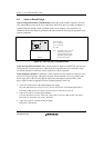
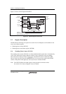
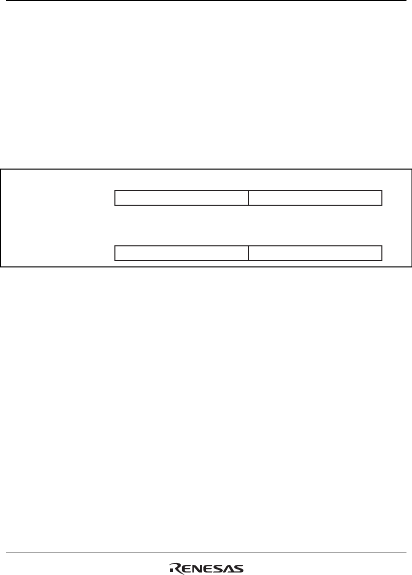
Writing to WTCNT and WTCSR: These registers must be written by a word transfer
instruction. They cannot be written by a byte or longword transfer instruction. When writing to
WTCNT, set the upper byte to H'5A and transfer the lower byte as the write data, as shown in
figure 5.2. When writing to WTCSR, set the upper byte to H'A5 and transfer the lower byte as the
write data. This transfer procedure writes the lower byte data to WTCNT or WTCSR.
15 8 7 0
H'5A Write data
Address: H'A415FF84
WTCNT write
15 8 7 0
H'A5 Write data
Address: H'A415FF86
WTCSR write
Figure 5.2 Writing to WTCNT and WTCSR
5.3 Use of the WDT
5.3.1 Canceling Standbys
The WDT can be used to cancel standby mode with an interrupt such as an NMI interrupt. The
procedure is described below. (The WDT does not operate when resets are used for canceling, so
keep the RESETP or RESETM pin low until the clock stabilizes.)
1. Before transitioning to standby mode, always clear the TME bit in WTCSR to 0. When the
TME bit is 1, an erroneous reset or interval timer interrupt may be generated when the count
overflows.
2. Set the type of count clock used in the CKS2 to CKS0 bits in WTCSR and the initial values for
the counter in the WTCNT. These values should ensure that the time till count overflow is
longer than the clock oscillation settling time.
3. The execution of a SLEEP instruction after the STBY bit of the standby control register
(STBCR: see section 6, Power-Down Modes) puts the system in standby mode and clock
operation then stops.
4. The WDT starts counting by detecting the edge change of the NMI signal.